Continuing my CCNA journey I’d like to address inter VLAN switching in a more detailed way. In this post I’ll configure my previous topology to use VTP and let STP prevent frame looping and other “anomalies” on Layer 2.
Updated network topology
 1
 2
 3
 4
 5
 6
 7
 8
 9
10
11
12
13
14
15
16
17
18
19
20
21
22
23
24
25
26
27
28
29
30
31
32
33
34
35
36
37
|
%%blockdiag
# <!-- collapse=True -->
diagram admin {↔

    PC1 [shape = "cisco.pc"];
    PC2 [shape = "cisco.pc"];
    PC3 [shape = "cisco.pc"];
    PC4 [shape = "cisco.pc"];
    PC5 [shape = "cisco.pc"];
    PC6 [shape = "cisco.pc"];

    SW4 <-> SW1, SW2, SW3 [color = "red", style="dotted"];
    SW1 <-> SW2 [folded];
    SW2 <-> SW3 [folded];


    group {
        label = "VLAN 10";
        color = "#FFF";
        SW1 <-> PC1;
        SW1 <-> PC2;
    }

    group {
        label = "VLAN 20";
        color = "#FFF";
        SW2 <-> PC3;
        SW2 <-> PC4;
    }

    group {
        label = "VLAN 10 + VLAN 20";
        color = "#FFF";
        SW3 <-> PC5;
        SW3 <-> PC6;
    }
}
|
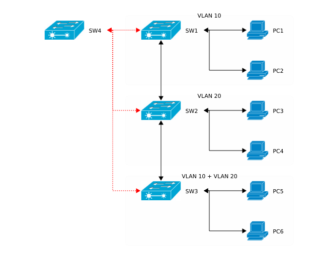
The new added component SW4 is connected to all other switches (red lines). Since a new switch has been added we’ll have to add the existing VLANs to the corresponding interfaces as well. But this time I won’t configure the ports manually. Instead I’ll use a Cisco proprietary protocol called VTP to exchange information about VLAN accross all available switches. So called VTP advertisements can be sent over ISL or 802.1Q (dot1q). Now let’s have a look at the process of adding VTP to the existing infrastructure.
VLAN Trunking Protocol
VTP has 3 operation modes:
- VTP server mode
- By default all Cisco switches are in server mode
- VLANs are stored on a device in a file called
vlan.dat
- In server mode changes to the file are allowed
- These changes/modifications are carried down to the clients as VTP advertisements
- VTP client mode
- Will listen to the changes sent by the server and apply the changes
- Is not allowed to modify the file
vlan.dat
- VTP transparent mode
- Will relay/forward VTP advertisemnts to downstream clients
- BUT will not apply the changes
- IS allowed to add/delete VLANs
- CAN modify its
vlan.dat
For my purpose I’ll chose following setup:
SW1 in VTP server mode- all others switches in client mode
 1
 2
 3
 4
 5
 6
 7
 8
 9
10
11
12
13
14
15
16
17
18
19
20
21
22
23
24
25
26
27
28
|
SW1>enable
Password:
SW1#conf t
Enter configuration commands, one per line.  End with CNTL/Z.
SW1(config)#vtp mode server
Device mode already VTP SERVER.

SW1(config)#vtp domain ccna-lab
Changing VTP domain name from NULL to ccna-lab

SW1(config)#vtp password ccna
Setting device VLAN database password to ccna

SW1(config)#vtp version 2

SW1(config)#do show vtp status
VTP Version                     : 2
Configuration Revision          : 6
Maximum VLANs supported locally : 255
Number of existing VLANs        : 8
VTP Operating Mode              : Server
VTP Domain Name                 : ccna-lab
VTP Pruning Mode                : Disabled
VTP V2 Mode                     : Disabled
VTP Traps Generation            : Disabled
MD5 digest                      : 0x8D 0xCD 0x81 0x32 0xF5 0xBA 0x71 0x33
Configuration last modified by 0.0.0.0 at 3-1-93 01:14:24
Local updater ID is 30.30.30.1 on interface Vl30 (lowest numbered VLAN interface found)
|
The configuration of the remaining switches is pretty straight-forward. Let’s have a look at an example (in this case SW2):
 1
 2
 3
 4
 5
 6
 7
 8
 9
10
11
12
13
14
15
16
17
18
19
20
21
22
23
|
SW2#conf t
Enter configuration commands, one per line.  End with CNTL/Z.
SW2(config)#vtp domain ccna-lab
Domain name already set to ccna-lab.

SW2(config)#vtp pass ccna
Setting device VLAN database password to ccna

SW2(config)#vtp mode client
Setting device to VTP CLIENT mode.

SW2(config)#do show vtp status
VTP Version                     : 2
Configuration Revision          : 7
Maximum VLANs supported locally : 255
Number of existing VLANs        : 8
VTP Operating Mode              : Client
VTP Domain Name                 : ccna-lab
VTP Pruning Mode                : Disabled
VTP V2 Mode                     : Disabled
VTP Traps Generation            : Disabled
MD5 digest                      : 0xD4 0x40 0x89 0x49 0x1A 0x6E 0x7A 0xBE
Configuration last modified by 30.30.30.1 at 3-1-93 01:04:21
|
Testing setup
In order to test the configuration I’ll add VLAN 40 (Testing) on SW1 and check if that gets advertised:
1
2
|
SW1(config)#vlan 40
SW1(config-vlan)#name Testing
|
Right after we verify if the clients got the VTP advertisements:
1
2
3
4
5
6
|
SW4#sh vlan brief

VLAN Name                             Status    Ports
...
40   Testing                          active
...
|
If I again delete VLAN 40 from SW1 then the clients should delete it as well:
And now test it:
 1
 2
 3
 4
 5
 6
 7
 8
 9
10
11
12
13
14
15
16
17
|
SW2#sh vlan brief

VLAN Name                             Status    Ports
---- -------------------------------- --------- -------------------------------
1    default                          active    Fa0/6, Fa0/7, Fa0/8, Fa0/9
                                                Fa0/10, Fa0/11, Fa0/12, Fa0/13
                                                Fa0/14, Fa0/15, Fa0/16, Fa0/17
                                                Fa0/18, Fa0/19, Fa0/20, Fa0/21
                                                Fa0/22, Fa0/23, Fa0/24, Gig0/1
                                                Gig0/2
10   Students                         active
20   Teachers                         active    Fa0/3, Fa0/4
30   Management                       active
1002 fddi-default                     active
1003 token-ring-default               active
1004 fddinet-default                  active
1005 trnet-default                    active
|
Spanning Tree Protocol
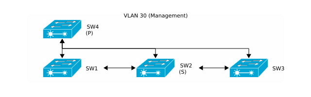
Since we now have to deal with interconnected switches and frame looping might be an issue, activating STP (Spanning Tree Protocol) will help mitigate the impacts of broadcast storms or multiple frame tranmissions. Cisco devices usually use Per VLAN Spanning Tree Protocol (PVST+, PVSTP) which is proprietary. The biggest difference to the “normal” STP (802.1D) is that PVST+ creates a different topology per VLAN. That means you can elect different roots (and thus different topology) for every available VLAN. Let’s have a look at the desired topology for VLAN 30 (Management):
 1
 2
 3
 4
 5
 6
 7
 8
 9
10
11
12
13
14
|
%%blockdiag
# <!-- collapse=True -->
diagram admin {↔


    group {
        label = "VLAN 30 (Management)"
        orientation = portrait;
        color = "#FFF"
        SW4 <-> SW1, SW2, SW3;
        SW1 <-> SW2 [folded];
        SW2 <-> SW3 [folded];
    }
}
|
Root(s) election
In terms of STP SW4 will be the primary (p) and SW2 the secondary (s) root. Let’s configure Sw4 and Sw2:
1
2
3
4
5
|
! SW4 configuration
SW4(config)#spanning-tree vlan 30 root primary

! SW2 configuration
SW2(config)#spanning-tree vlan 30 root secondary
|
And now let’s have a look at the port connectivity matrix:
| |
SW1 |
SW2 |
SW3 |
SW4 |
| SW1 |
- |
Fa0/1 - Fa0/1 |
- |
Fa0/4 - Fa0/1 |
| SW2 |
Fa0/1 - Fa0/1 |
- |
Fa0/2 - Fa0/1 |
Fa0/5 - Fa0/3 |
| SW3 |
- |
Fa0/1 - Fa0/2 |
- |
Fa0/4, Fa0/5 - Fa0/2, Fa0/4 |
| SW4 |
Fa0/1 - Fa0/4 |
Fa0/3 - Fa0/5 |
Fa0/2, Fa0/4 - Fa0/4, Fa0/5 |
- |
So SW1 (Fa0/1) is connected to SW2 (Fa0/1), SW3 (Fa0/3) is connected to SW2 (Fa0/2) and so on. You may have noticed that SW3 and SW4 are connected to each other using 4 ports. In that case we have a redundant connection between both switches. In this case we’ll later on configure the redundant connection as an EtherChannel.
Testing the STP configuration
And now let’s have a look at the STP information:
 1
 2
 3
 4
 5
 6
 7
 8
 9
10
11
12
13
14
15
16
17
18
19
|
SW2#sh spanning-tree vlan 30
VLAN0030
  Spanning tree enabled protocol ieee
  Root ID    Priority    20510
             Address     00E0.F96C.2E07
             Cost        19
             Port        5(FastEthernet0/5)
             Hello Time  2 sec  Max Age 20 sec  Forward Delay 15 sec

  Bridge ID  Priority    28702  (priority 28672 sys-id-ext 30)
             Address     0030.F222.3EE5
             Hello Time  2 sec  Max Age 20 sec  Forward Delay 15 sec
             Aging Time  20

Interface        Role Sts Cost      Prio.Nbr Type
---------------- ---- --- --------- -------- --------------------------------
Fa0/1            Desg FWD 19        128.1    P2p
Fa0/2            Altn BLK 19        128.2    P2p
Fa0/5            Root FWD 19        128.5    P2p
|
We can notice that:
- The root has a MAC address of
00E0.F96C.2E07
FastEthernet 0/5 is the root port with a cost of 19 and is in forwarding stateFastEthernet 0/2 is in blocking stateFastEthernet 0/1 is the designated port
 1
 2
 3
 4
 5
 6
 7
 8
 9
10
11
12
13
14
15
16
17
18
|
SW4#sh spanning-tree vlan 30
VLAN0030
  Spanning tree enabled protocol ieee
  Root ID    Priority    20510
             Address     00E0.F96C.2E07
             This bridge is the root
             Hello Time  2 sec  Max Age 20 sec  Forward Delay 15 sec

  Bridge ID  Priority    20510  (priority 20480 sys-id-ext 30)
             Address     00E0.F96C.2E07
             Hello Time  2 sec  Max Age 20 sec  Forward Delay 15 sec
             Aging Time  20

Interface        Role Sts Cost      Prio.Nbr Type
---------------- ---- --- --------- -------- --------------------------------
Fa0/1            Desg FWD 19        128.1    P2p
Fa0/3            Desg FWD 19        128.3    P2p
Po1              Desg FWD 9         128.27   Shr
|
We can notice that:
- This is indeed the root (“This bridge is the root”)
- All available ports are designated and in forwarding state (the root has no root port)
 1
 2
 3
 4
 5
 6
 7
 8
 9
10
11
12
13
14
15
16
17
18
|
SW3#sh spanning-tree vlan 30
VLAN0030
  Spanning tree enabled protocol ieee
  Root ID    Priority    20510
             Address     00E0.F96C.2E07
             Cost        9
             Port        27(Port-channel 2)
             Hello Time  2 sec  Max Age 20 sec  Forward Delay 15 sec

  Bridge ID  Priority    32798  (priority 32768 sys-id-ext 30)
             Address     0003.E481.688D
             Hello Time  2 sec  Max Age 20 sec  Forward Delay 15 sec
             Aging Time  20

Interface        Role Sts Cost      Prio.Nbr Type
---------------- ---- --- --------- -------- --------------------------------
Fa0/1            Desg FWD 19        128.1    P2p
Po2              Root FWD 9         128.27   Shr
|
We can notice that:
Po2 is the root port with a cost of 9 and in forwarding stateFastEthernet 0/1 is a designated port with a cost of 19 and in forwarding state
Port cost
Now you may have noticed the diffrent port costs. A port cost is an integer assigned to each interface per VLAN for providing a good way for measuring a port’s connectivity.
| Ethernet |
Cost |
| 10 Mbps |
100 |
| 100 Mbps |
19 |
| 1 Gbps |
4 |
| 10 Gbps |
2 |
So because most of the ports are FastEthernet ports they will get a port cost of 19 (when connected directly to the root).
EtherChannel
As previosuly mentioned there are 2 port links between SW3 and SW4. EtherChannel provides a way to prevent convergence (STP) when a single port or cable failure occurs. The switches will treat the EtherChannel as a single interface. The big advantage is that if one of the links fails, STP convergence does not have to occur if at least one of the links is up. Besides that the switches will now have a load-balancing effect which will spread the traffic load accross the active links in the (Ether)channel.
Manual EtherChannel
So when using EtherChannels STP will operate on the EtherChannel itself rather than on the individual physical links. STP will then either forward or block traffic on the entire logical EtherChannel for a specific VLAN. Probably the most simple way to activate EtherChannel is to put the physical interfaces into the same channel-group. Let’s have a look how this is done:
 1
 2
 3
 4
 5
 6
 7
 8
 9
10
11
12
13
|
SW3(config)#int f0/4
SW3(config-if)#channel-group 1 mode on
SW3(config-if)#
%LINK-5-CHANGED: Interface Port-channel 1, changed state to up

%LINEPROTO-5-UPDOWN: Line protocol on Interface Port-channel 1, changed state to up

SW3(config-if)#int f0/5
SW3(config-if)#channel-group 1 mode on
SW3(config-if)#
%LINK-5-CHANGED: Interface Port-channel 2, changed state to down

%LINEPROTO-5-UPDOWN: Line protocol on Interface Port-channel 2, changed state to down
|
And now for SW4:
 1
 2
 3
 4
 5
 6
 7
 8
 9
10
11
12
13
|
SW4(config)#int f0/2
SW4(config-if)#channel-group 2 mode on
SW4(config-if)#
%LINK-5-CHANGED: Interface Port-channel 2, changed state to up

%LINEPROTO-5-UPDOWN: Line protocol on Interface Port-channel 2, changed state to up

SW4(config-if)#int f0/4
SW4(config-if)#channel-group 2 mode on
SW4(config-if)#
%LINK-5-CHANGED: Interface Port-channel 1, changed state to down

%LINEPROTO-5-UPDOWN: Line protocol on Interface Port-channel 1, changed state to down
|
If you don’t want to manually configure the EtherChannel, one can let the switches negotiate the configuration for it. Cisco switches support
- Cisco proprietary Port Aggregation Protocol (PAgP)
- Enabled by the keywords desirable and auto
- IEEE standard Link Aggregation Control Protocol (LACP)
- Enabled by the keywords passive and active
So when using PAgP at least one side must use desirable or active when using LACP. Let’s have some look at one example (PAgP):
1
2
3
4
|
SW3(config)#int f0/4
SW3(config-if)#channel-group 2 mode desirable
SW3(config-if)#int f0/5
SW3(config-if)#channel-group 2 mode desirable
|
1
2
3
4
|
SW4(config)#int f0/2
SW4(config-if)#channel-group 1 mode auto
SW4(config-if)#int f0/5
SW4(config-if)#channel-group 1 mode auto
|
Testing EtherChannel connectivity
Now let’s see of the port channels are working well:
 1
 2
 3
 4
 5
 6
 7
 8
 9
10
11
12
13
14
15
16
17
18
19
|
SW4#sh eth sum
Flags:  D - down        P - in port-channel
        I - stand-alone s - suspended
        H - Hot-standby (LACP only)
        R - Layer3      S - Layer2
        U - in use      f - failed to allocate aggregator
        u - unsuitable for bundling
        w - waiting to be aggregated
        d - default port


Number of channel-groups in use: 2
Number of aggregators:           2

Group  Port-channel  Protocol    Ports
------|-------------|-----------|----------------------------------------------

1      Po1(SU)           -      Fa0/4(P) Fa0/2(P)
2      Po2(SD)           -
|
As you can see there is a port-channel Po1 consisting of Fa0/2 and Fa0/4. The port.channel is also working and in use.
 1
 2
 3
 4
 5
 6
 7
 8
 9
10
11
12
13
14
15
16
17
18
19
|
SW3#sh eth sum
Flags:  D - down        P - in port-channel
        I - stand-alone s - suspended
        H - Hot-standby (LACP only)
        R - Layer3      S - Layer2
        U - in use      f - failed to allocate aggregator
        u - unsuitable for bundling
        w - waiting to be aggregated
        d - default port


Number of channel-groups in use: 2
Number of aggregators:           2

Group  Port-channel  Protocol    Ports
------|-------------|-----------|----------------------------------------------

1      Po1(SD)           -
2      Po2(SU)           -      Fa0/4(P) Fa0/5(P)
|
Again Po2 is a working port-channel and consists of Fa0/4 and Fa0/5.
You also should have noticed that the ports on each switch belong to different channel groups. You can now treat Po1 and Po2 as interfaces, bring them up or down. If your port-channel is down, do following:
1
2
|
SW4(config)#int Po1
SW4(config-if)#no shutdown
|
You can also add VLANs to it:
1
2
|
SW4(config-if)#switchport mode trunk
SW4(config-if)#switchport trunk allowed vlan 10,20,30
|
Afterwards you should be able to verify that:
 1
 2
 3
 4
 5
 6
 7
 8
 9
10
11
12
13
14
15
16
17
18
19
20
|
SW4#sh int trunk
Port        Mode         Encapsulation  Status        Native vlan
Fa0/1       on           802.1q         trunking      1
Fa0/3       on           802.1q         trunking      1
Po1         on           802.1q         trunking      1

Port        Vlans allowed on trunk
Fa0/1       10,20,30
Fa0/3       10,20,30
Po1         10,20,30

Port        Vlans allowed and active in management domain
Fa0/1       10,20,30
Fa0/3       10,20,30
Po1         10,20,30

Port        Vlans in spanning tree forwarding state and not pruned
Fa0/1       10,20,30
Fa0/3       10,20,30
Po1         10,20,30
|
Troubleshooting
Although this is not a complex topology, adding STP to your switches, might increase the troubleshooting steps needed to localize your problem. In my particular case I was able to ping from PC3 to PC6, however PC1 wasn’t able to reach PC5. After eliminating a list of might-be problems like:
- port security
- misconfigured trunk ports
- wrong VLANs
- missing IP addresses
I was able to nail down the problem using STP related information. Furthermore it turned out that the EtherChannel was not working at all, causing certain frames to be dropped without reaching their final destination. So how might one guess how data would be routed based on output from the show commands?
Let’s suppose PC1 (10.10.10.101) cannot reach PC5 (10.10.10.105). Also keep in mind that both hosts belong to the same VLAN (10 = Students). Our simplified topology would look like this:
 1
 2
 3
 4
 5
 6
 7
 8
 9
10
11
12
13
14
15
16
17
18
19
|
%%dot
# <!-- collapse=True -->↔

     SW1 -- SW2 [dir=both, label = "Fa0/1 - Fa0/1", arrowhead=normal];
     SW2 -- SW3 [dir=both, label = "Fa0/2 - Fa0/1", arrowhead=normal];

     SW4 -- SW1 [dir=both, label = "Fa0/4 - Fa0/1"];
     SW4 -- SW2 [dir=both,label = "Fa0/3 - Fa0/5"];
     SW4 -- SW3 [dir=both,label = "Po1 - Po2", arrowhead=normal];

     PC1 [label = "PC1 [.101]"];
     PC4 [label = "PC5 [.105]"];

     SW1 -- PC1 [dir=both, label = "Fa0/2 - Fa0"];
     SW3 -- PC4 [dir=both, label = "Fa0/3 - Fa0"];

     {rank = same; SW1; SW2; SW3;}
     {rank = same; PC1; PC4;}
 }
|

There are several way how frames from PC1 would reach PC5. However when dealing with STP some ports will in be blocking state. Let’s check that out:
 1
 2
 3
 4
 5
 6
 7
 8
 9
10
|
SW1#sh spanning-tree vlan 10
VLAN0010
...

Interface        Role Sts Cost      Prio.Nbr Type
---------------- ---- --- --------- -------- --------------------------------
Fa0/1            Altn BLK 19        128.1    P2p
Fa0/2            Desg FWD 19        128.2    P2p
Fa0/3            Desg FWD 19        128.3    P2p
Fa0/4            Root FWD 19        128.4    P2p
|
 1
 2
 3
 4
 5
 6
 7
 8
 9
10
|
SW2#sh spanning-tree vlan 10
VLAN0010
...

Interface        Role Sts Cost      Prio.Nbr Type
---------------- ---- --- --------- -------- --------------------------------
Fa0/1            Desg FWD 19        128.1    P2p
Fa0/2            Root FWD 19        128.2    P2p
Fa0/5            Altn BLK 19        128.5    P2p
Fa0/6            Desg FWD 19        128.6    P2p
|
1
2
3
4
5
6
7
8
|
SW3#sh spanning-tree vlan 10
...

Interface        Role Sts Cost      Prio.Nbr Type
---------------- ---- --- --------- -------- --------------------------------
Fa0/1            Desg FWD 19        128.1    P2p
Fa0/3            Desg FWD 19        128.3    P2p
Po2              Desg FWD 9         128.27   Shr
|
1
2
3
4
5
6
7
8
9
|
SW4#sh spanning-tree vlan 10
...

Interface        Role Sts Cost      Prio.Nbr Type
---------------- ---- --- --------- -------- --------------------------------
Fa0/1            Desg FWD 19        128.1    P2p
Fa0/3            Desg FWD 19        128.3    P2p
Fa0/5            Desg FWD 19        128.5    P2p
Po1              Root FWD 9         128.27   Shr
|
Based of the previous outputs our topology now looks like this:
 1
 2
 3
 4
 5
 6
 7
 8
 9
10
11
12
13
14
15
16
17
18
19
|
%%dot
# <!-- collapse=True -->↔

     SW1 -- SW2 [dir=both, arrowtail=box];
     SW2 -- SW3 [dir=both, arrowhead=normal];

     SW4 -- SW1 [dir=both];
     SW4 -- SW2 [dir=both, arrowhead=box];
     SW4 -- SW3 [dir=both, arrowhead=normal];

     PC1 [label = "PC1 [.101]"];
     PC4 [label = "PC5 [.105]"];

     SW1 -- PC1 [dir=both];
     SW3 -- PC4 [dir=both];

     {rank = same; SW1; SW2; SW3;}
     {rank = same; PC1; PC4;}
 }
|

That means:
SW1s Fa0/1 port is in blocking state (arrow endpoint is a box)SW2s Fa0/5 port is in blocking state (arrow endpoint is a box)- all other ports are in forwarding state
In this case there is only one way PC1 could send frames to PC5 (red lines):
 1
 2
 3
 4
 5
 6
 7
 8
 9
10
11
12
13
14
15
16
17
18
19
20
|
%%dot
# <!-- collapse=True -->
 graph mylab {↔

     SW1 -- SW2 [dir=both, arrowtail=box];
     SW2 -- SW3 [dir=both, arrowhead=normal];

     SW4 -- SW1 [dir=both, color="red"];
     SW4 -- SW2 [dir=both, arrowhead=box];
     SW4 -- SW3 [dir=both, arrowhead=normal, color="red"];

     PC1 [label = "PC1 [.101]"];
     PC4 [label = "PC5 [.105]"];

     SW1 -- PC1 [dir=both, color="red"];
     SW3 -- PC4 [dir=both, color="red"];

     {rank = same; SW1; SW2; SW3;}
     {rank = same; PC1; PC4;}
 }
|

In the next posts I’ll deal with IP routing on Layer 3.