This article is part of a series.
- Part 1: Documentation as Code for Cloud
- Part 2: Documentation as Code for Cloud - PlantUML
- Part 3: This Article
Introduction #
In the last post, I’ve used PlantUML to draw things like groups, accounts, and clusters. However, I didn’t focus on how different parts inside the business layer interact (usually components related to the main application/system relevant for your business). Now, we’ll use a DSL Domain-Specific Language specific for this use case to show these interactions between components, services, and systems. I’ll use the C4 model to show the same system in different ways based on who we’re showing it to. It allows us to adjust how much detail we include.
C4 Model #
The C4 model was developed by Simon Brown as a means of providing a visual map of system components across four levels of abstraction, as suggested by its title. Each level of abstraction in the C4 model suits different audiences, from the non-technical management level to detailed developer perspectives, each level of abstraction is tailored to meet its observer’s understanding. To maintain consistency when describing the system design, the C4 model uniformly applies the same terminology and abstractions across all its levels, effectively implementing ubiquitous language principles from Domain-Driven Design (DDD).
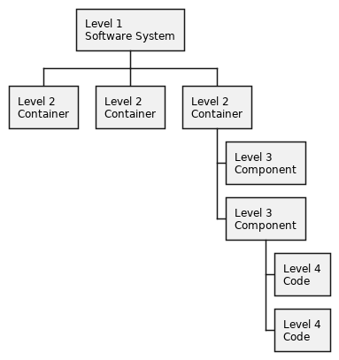
Abstractions #
The C4 model uses abstractions to form an hierarchy of well-defined diagrams (at different levels). Currently these abstractions are available:
-
Person
- Represents human users interacting with the system (e.g., Administrator, End User, Customer).
-
System
- A top-level view showing different people interacting with different software systems. (e.g., E-commerce Platform, Payment Gateway, our self-destructing email service 😎).
-
Container
- Involves zooming into an individual system to reveal containers within. Examples include server-side applications, client-side applications, databases, etc.
- not to be confused with Docker containers
-
Component
- Dives deeper into an individual container to expose its components, like classes, interfaces or objects in your code.
Diagram types #
Level 1: Context diagram #
Shows how your system fits into the larger system environment (system landscape). It basically shows interactions between users and systems:
- e.g. A payment system interacting with an user and a banking system
Level 2: Container diagram #
Higher level view within a system itself. Shows software “containers” like web servers, standalone apps, or databases. (e.g., An API server, a database, and a client app in a single system)
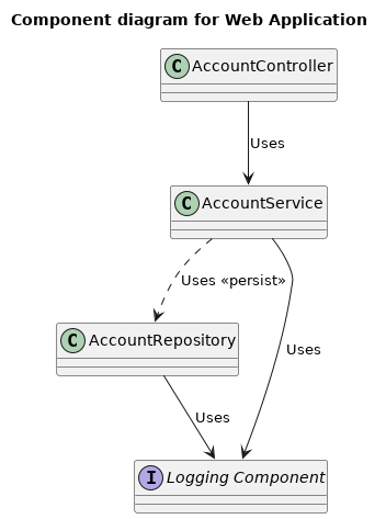
Level 3: Component diagram #
Shows internal parts of a container. Mostly used with complex software. (e.g., Controllers, services, repositories inside of a web application)
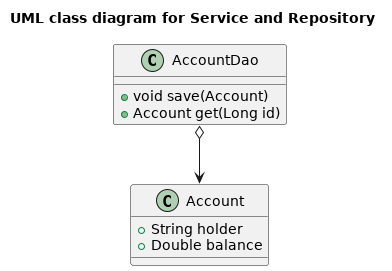
Level 4: Code diagram #
A detailed view of the code level. For systems with little internal complexity, it can be skipped. (e.g., UML class diagrams)
Structurizr DSL #
Structurizr is used for describing and visualizing architecture using the C4 model. One of the main selling points is the fact you can define an entire (IT) architecture model using text. A typical model consists of:
- relationships between abstractions
- different views
Let’s have a look at a simple example:
|
|
What do we have?
- Entities:
- “User”: a person who uses the “Web Application”.
- “Web Application”: a software system tagged as “System”.
- “Database”: another software system tagged as “Database”.
- “Development Team”: a person representing the team that develops the “Web Application”.
- Relationships:
- The “User” uses the “Web Application”.
- Container View:
- Focused on “Web Application”.
- Includes all elements in the model.
- Uses automatic layout.
- Styles:
- The “Database” elements are colored in blue ("#0000ff").
Before we move on, let’s briefly discuss the installation steps.
Installation #
I’d suggest you use the Docker image for a safe playground:
|
|
This will fetch the structurizr/lite Docker image from Dockerhub, start the container, mount the current working
directory to /usr/local/structurizr and setup a port forwarding from localhost:1337 to <docker container>:8000.
👉 I’ve setup a github repository with the code I’ll be using in the next sections. Feel free to clone from https://github.com/dorneanu/ripmail.
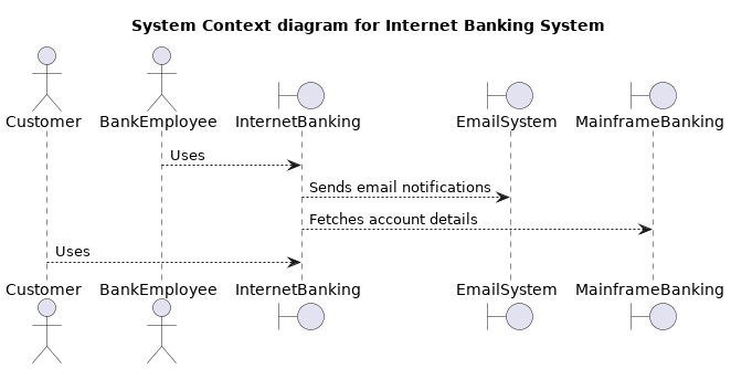
Short recap #
If you recall my initial post the entire aim was to document a hypothetical self-destructing e-mail service. In my 2nd blog post (about PlantUML) I’ve generated following sequence diagram:
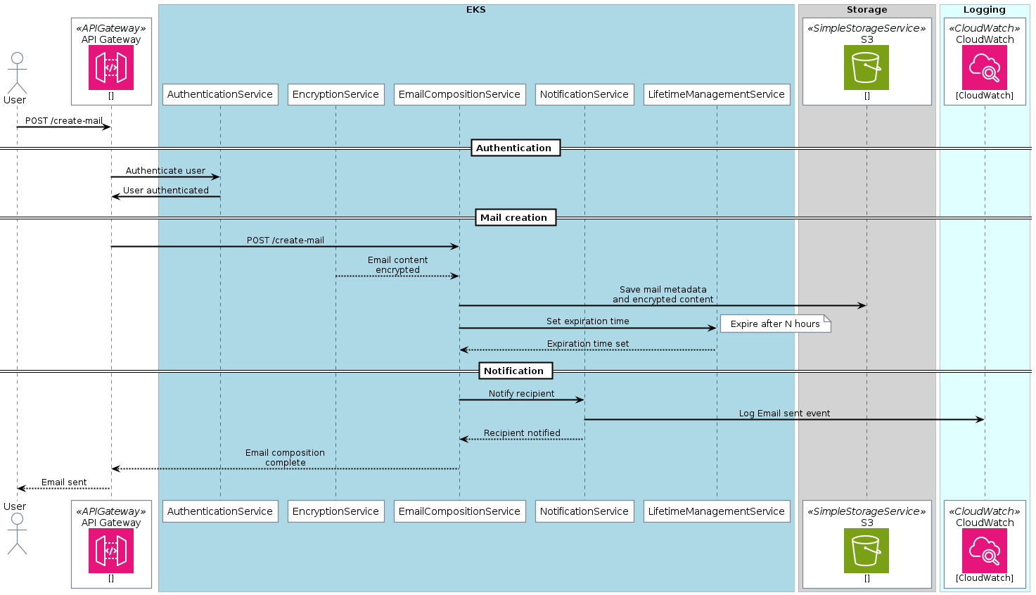
In the following I’ll try to implement exactly this workflow using C4 and Structurizr DSL.
ripmail #
👉 Checkout the code at https://github.com/dorneanu/ripmail.
Model #
Let’s start with the basic construct:
|
|
So, what do we have?
- ❶
workspace- Defines the workspace for a self-destructing email service.
- ❷
model- This has to be implemented but basically it’s a
- Placeholder section where you’d define the elements (software systems, people, containers) and their relations.
- ➌
views- A System Landscape view ❺ that includes all elements defined in the model.
- The specified theme ❻ comes from an external JSON file, allowing broad customization of the look-and-feel.
- Three styles are defined for different types of elements labeled as Person, Sender, and Recipient. These characters are all represented by the Person shape.
Let’s focus more on the model:
|
|
We have following elements and groups:
- ❶ Sender: Person who creates the self-destructing email.
- ❷ Recipient: Person who receives the self-destructing email.
- ➌ Self-Destructing Email Service: Represents the overall service/system being described.
Additionally we have these systems inside the group:
- ❹ Logging System: Keeps track of events related to mail creation.
- ❺ Storage System: Stored encrypted email content. Includes a Storage Backend container.
- ❻ Notification System: Sends notification to recipient. Contains a Notification Service group with a Notification API container.
Main backend system #
Now the backend system responsible for the business logic:
|
|
The Backend System is the core system, with business logic, for creating/dispatching self-destructing mails. of following containers and services:
- ❷ Web Application: The frontend component within the backend system for creating mails.
- ➌ Authentication Service: Group handling user credential verification.
- ❹ Auth Service API: Provides interface for authentication service.
- ❺ Auth Service Database: Stores user credential data.
- ❻ Auth Service API->Auth Service Database: Indicates API checks credentials against this database.
- ❼ Email Composition Service: Group handling creation/storage of emails.
- ❽ Email Composition API: Interface for the email composition service.
- ❾ Email Composition Database: Stores meta-information of emails.
- ❿ Email Composition API -> Email Composition Database: Indicates API stores mail metadata in this database.
- ⓫ View Email Service: Group handling email display.
- ⓬ Email View Frontend: The frontend component withing the backend system for viewing emails.
Relationships #
And finally the relationships between different components:
|
|
| From | To | Description |
|---|---|---|
| Mail Composition API | Storage | Store mail metadata and encrypted content |
| Mail Composition API | Notification API | Notify recipient |
| Notification API | Mail Composition API | Recipient notified |
| Notification API | Logging | Log Email sent event |
| Sender | Web Application | Create new mail |
| Web Application | Auth API | Authenticate user |
| Web Application | Mail Composition API | Create mails |
| Notification | Recipient | Send out notification |
| Backend System | Logging | Create events |
| Recipient | Web Application | View self-destructing mail |
| Web Application | View Email Frontend | View email |
| View Email Frontend | MailDB | Fetches email data for visualization |
| View Email Frontend | Storage | Fetches email details for visualization |
Deployments #
Deployment components are required for the deployment diagrams. These illustrate how software systems are deployed onto infrastructure elements in an environment. They also enable you to visualize how containers within a system map onto the infrastructure.
This kind of diagrams are very important as they provide important information regarding system runtime environment such as scaling, redundancy, network topology, and communication protocols. They are crucial to understanding the physical aspects and deployment context of a system.
|
|
We’re still defining the model. Now we have defined a deploymentEnvironment live ❶ which should be deployed into the AWS
Cloud ❷, namely in eu-central-1 ➌. In this region we’ll have different organizational units (OUs):
-
OU: Tech
This will host the EKS cluster as well as the API Gateway which serves as the main entrypoint for API calls.
-
OU: Security
This is where alert & monitoring will take place. Also here relevant data to the mail will be stored within S3 buckets. Finally we use IAM capabilities to make sure authentication and authorization works properly.
-
OU: DevOps
The CI/CD build pipeline and infrastructure provisioning will take place here. The software artefacts will be built here and deployed into the accounts inside “OU: Tech”.
|
|
-
OU: DevOps
But one thing at a time:
1 2 3 4 5 6 7 8 9 10 11 12 13 14 15 16 17 18 19// -------------------------------------------- // Organizational Unit: DevOps // -------------------------------------------- deploymentNode "OU-DevOps" { ❶ tags "Amazon Web Services - AWS Organizations Organizational Unit" ❷ deploymentNode "acc-devops-prod" { ➌ tags "Amazon Web Services - AWS Organizations Account" ❹ vpc_management = deploymentNode "VPC (management)" { ❺ tags "Amazon Web Services - VPC Virtual private cloud VPC" ❻ gitlab_server = infrastructureNode "Gitlab Server" { ❼ tags "Amazon Web Services - EC2" } } } }Code Snippet 8: Deployment components for the OU DevOpsThe DevOps OU deployment components are:
- Organizational Unit (OU-DevOps): Represents a unit in the organization.
- ❶ Tagged as an Amazon Web Services (AWS) Organizations Organizational Unit.
- ❷ acc-devops-prod: Represents an account within the OU-DevOps unit.
- ➌ Tagged as an AWS Organizations Account.
- ❹ VPC (vpc_management): A Virtual Private Cloud (VPC) within the acc-devops-prod account.
- ❺ Tagged as an AWS VPC Virtual private cloud VPC.
- ❻ Gitlab Server (gitlab_server): Infrastructure node within the VPC.
- ❼ Tagged as AWS EC2.
- Organizational Unit (OU-DevOps): Represents a unit in the organization.
-
OU: Security
1 2 3 4 5 6 7 8 9 10 11 12 13 14 15 16 17 18 19 20 21 22 23 24 25 26// --------------------------------------------- // Organizational Unit: Security // --------------------------------------------- ❶ deploymentNode "OU-Security" { ❷ tags "Amazon Web Services - AWS Organizations Organizational Unit" ➌ deploymentNode "acc-security-logging" { ❹ tags "Amazon Web Services - AWS Organizations Account" ❺ s3_logging = infrastructureNode "S3 Bucket" { ❻ tags "Amazon Web Services - Simple Storage Service" } ❼ infrastructureNode "CloudWatch Logs" { ❽ tags "Amazon Web Services - CloudWatch Logs" } } ❾ deploymentNode "acc-security-monitoring" { ❿ tags "Amazon Web Services - AWS Organizations Account" ⓫ infrastructureNode "CloudWatch" { ⓬ tags "Amazon Web Services - CloudWatch Alarm" } } }Code Snippet 9: Deployment components for the OU SecurityThe Security OU deployment components are:
- Organizational Unit (OU-Security): Represents a security unit in the organization.
- ❶ Tagged as an AWS Organizations Organizational Unit.
- ➌ acc-security-logging: Represents an account within the OU-Security unit for logging purposes.
- ❹ Tagged as an AWS Organizations Account.
- ❺ Contains an “S3 Bucket” infrastructure node.
- ❻ Tagged as AWS Simple Storage Service.
- ❼ Contains a “CloudWatch Logs” infrastructure node.
- ❽ Tagged as AWS CloudWatch Logs.
- ❾ acc-security-monitoring: Represents another account within the OU-Security unit for monitoring purposes.
- ❿ Tagged as an AWS Organizations Account.
- ⓫ Contains a “CloudWatch” infrastructure node.
- ⓬ Tagged as AWS CloudWatch Alarm.
- Organizational Unit (OU-Security): Represents a security unit in the organization.
-
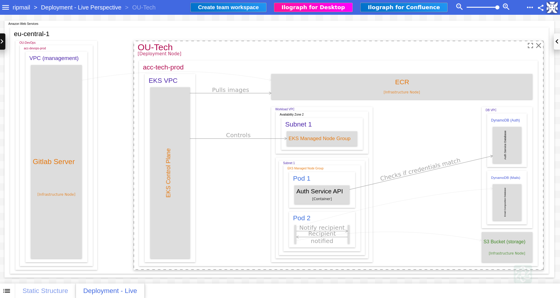
OU: TECH
Now the most complicated one:
1 2 3 4 5 6 7 8 9 10 11 12 13 14 15 16 17 18 19 20 21 22 23 24 25 26 27 28 29 30 31 32 33 34 35 36 37 38 39// -------------------------------------------- // Organizational Unit: Tech // -------------------------------------------- ❶ ou_tech = deploymentNode "OU-Tech" { tags "Amazon Web Services - AWS Organizations Organizational Unit" ❷ deploymentNode "acc-tech-prod" { tags "Amazon Web Services - AWS Organizations Account" // EKS control plane ➌ eks_vpc = deploymentNode "EKS VPC" { tags = "Amazon Web Services - VPC Virtual private cloud VPC" ❹ eks_control_plane = infrastructureNode "EKS Control Plane" { tags = "Amazon Web Services - EKS Cloud" } } // ECR ❺ ecr = infrastructureNode "ECR" { tags "Amazon Web Services - Elastic Container Registry" description "Private ECR registry" } // EKS cluster ❻ workload_vpc = deploymentNode "Workload VPC" {...} // DynamoDB instances ❼ dbs = group "Databases" {...} // S3 (Storage System) ❽ s3_storage = infrastructureNode "S3 Bucket (storage)" { tags "Amazon Web Services - Simple Storage Service" } } }Code Snippet 10: Deployment components for the OU TechThis will result in following components hierarchy:
- ❶ Organizational Unit (OU-Tech): Represents a technology unit within the organization.
- ❷ acc-tech-prod: Represents a production account within the “OU-Tech” unit.
- EKS control plane deployed within an EKS VPC.
- ➌ EKS VPC: VPC where the EKS control plane is deployed,
- ❹ EKS Control Plane: infrastructure node within EKS VPC.
- ❺ ECR: Infrastructure node for the Elastic Container Registry with private ECR registry.
- ❻ Workload VPC: Deployment node holding different workloads.
- ❼ Databases group holds DynamoDB instances.
- ❽ S3 Bucket (storage): Infrastructure node for the storage system.
- EKS control plane deployed within an EKS VPC.
Let’s have a look what’s inside the workload VPC:
1 2 3 4 5 6 7 8 9 10 11 12 13 14 15 16 17 18 19 20 21 22 23 24 25 26 27 28 29 30 31 32 33 34 35 36 37 38 39 40 41 42 43 44 45// EKS cluster workload_vpc = deploymentNode "Workload VPC" { tags = "Amazon Web Services - VPC Virtual private cloud VPC" // AZ 1 ❶ deploymentNode "Availability Zone 1" { tags = "Amazon Web Services - Region" ❷ deploymentNode "Subnet 1" { tags = "Amazon Web Services - VPC VPN Gateway" ➌ eks_node_group1 = deploymentNode "EKS Managed Node Group" { tags = "Amazon Web Services - EKS Cloud" ❹ eks_node_group1_pod1 = deploymentNode "Pod 1" { tags = "Kubernetes - pod" ❺ pod1_authAPI = containerInstance authAPI } ❻ eks_node_group1_pod2 = deploymentNode "Pod 2" { tags = "Kubernetes - pod" ❼ pod2_mailCompositionAPI = containerInstance mailcompositionAPI ❽ pod2_notificationAPI = containerInstance notificationAPI } } } } // AZ 2 ❾ deploymentNode "Availability Zone 2" { tags = "Amazon Web Services - Region" ❿ deploymentNode "Subnet 1" { tags = "Amazon Web Services - VPC VPN Gateway" ⓫ eks_node_group2 = infrastructureNode "EKS Managed Node Group" { tags = "Amazon Web Services - EKS Cloud" } } } }Code Snippet 11: Components of the workload VPCThe workload VPC consists of 2 availability zones:
- ❶ Availability Zone 1: A separate deployment node categorized as an AWS Region.
- ❷ Subnet 1: Deployment node within Availability Zone 1.
- ➌ EKS Managed Node Group: Node group for managing EKS resources.
- ❹ Pod 1: Deployment node within the EKS Managed Node Group.
- ❺ Houses instance of authAPI container.
- ❻ Pod 2: Another deployment node within the EKS Managed Node Group.
- ❼ Houses instance of mailcompositionAPI container.
- ❽ Houses instance of notificationAPI container.
- ❾ Availability Zone 2: Another separate deployment node categorized as an AWS Region.
- ❿ Subnet 1: Deployment node within Availability Zone 2.
- ⓫ EKS Managed Node Group: Infrastructure node for managing EKS resources.
Let’s also have a look how we can use
containerInstancefor the databases:1 2 3 4 5 6 7 8 9 10 11 12 13 14 15 16 17 18// DynamoDB instances ❶ dbs = group "Databases" { deploymentNode "DB VPC" { tags = "Amazon Web Services - VPC Virtual private cloud VPC" ❷ deploymentNode "DynamoDB (Auth)" { tags "Amazon Web Services - DynamoDB" ➌ liveUserDB = containerInstance authDB } ❹ deploymentNode "DynamoDB (Mails)" { tags "Amazon Web Services - DynamoDB" ❺ liveMailDB = containerInstance mailDB } } }Code Snippet 12: Components of the DB VPCThis will create:
- ❶ Databases: A group of databases within a DB VPC deployment node.
- ❷ DynamoDB (Auth): DynamoDB instance for authentication.
- ➌ Contains a live instance of authDB.
- ❹ DynamoDB (Mails): DynamoDB instance for mail metadata.
- ❺ Contains a live instance of mailDB.
Views #
Views in Structurizr are used to create visual diagrams of your software architecture model. They provide a way to communicate the different aspects of your system to various stakeholders. Views can be thought of as ‘camera angles’ on your architecture model, each designed to present a certain perspective of the system.
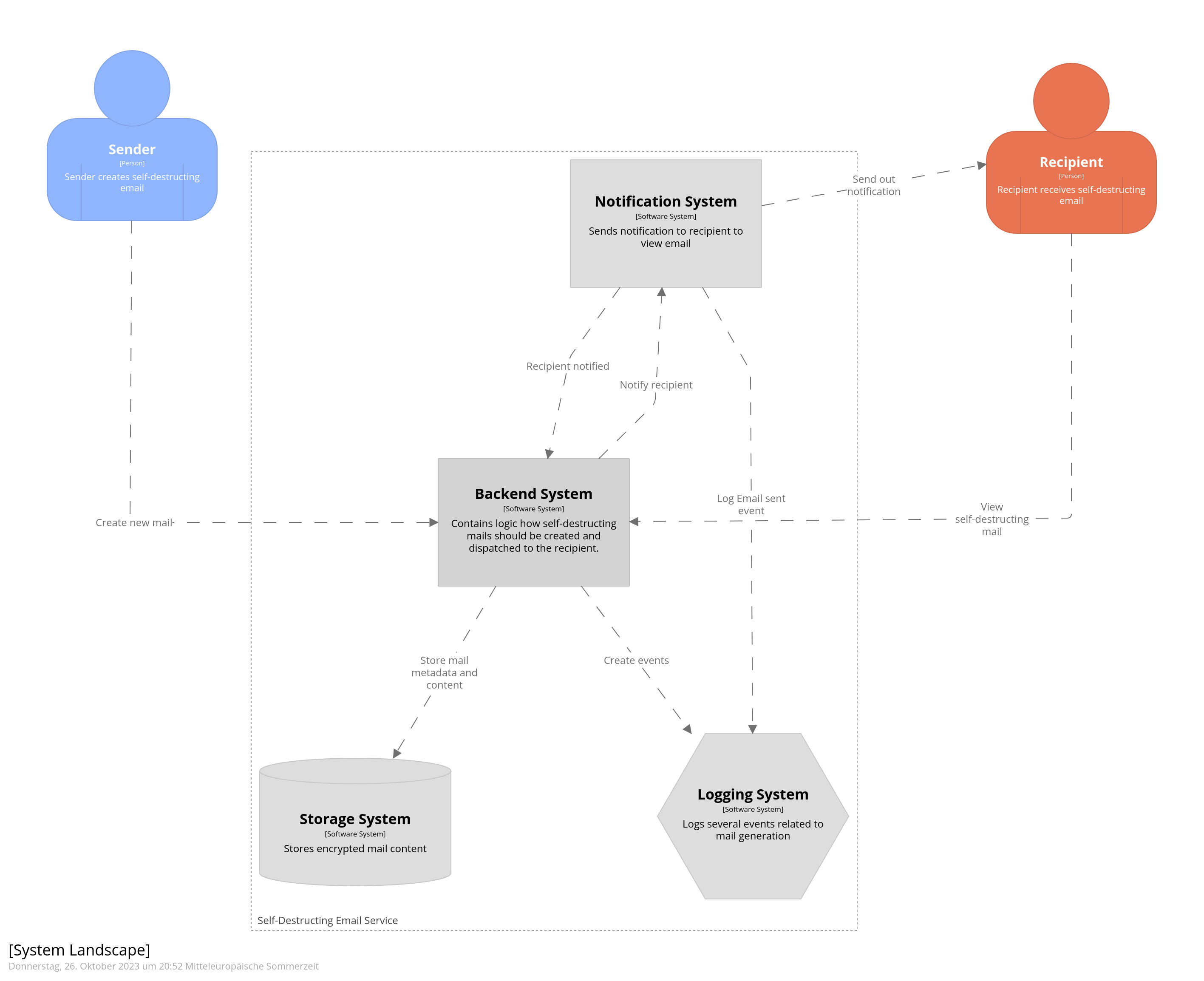
System Landscape #
The System Landscape view in Structurizr is the highest level view of a software system’s architecture. It shows all users, software systems and external systems or services in scope. It informs about the overall system context and interaction among systems and users.
|
|
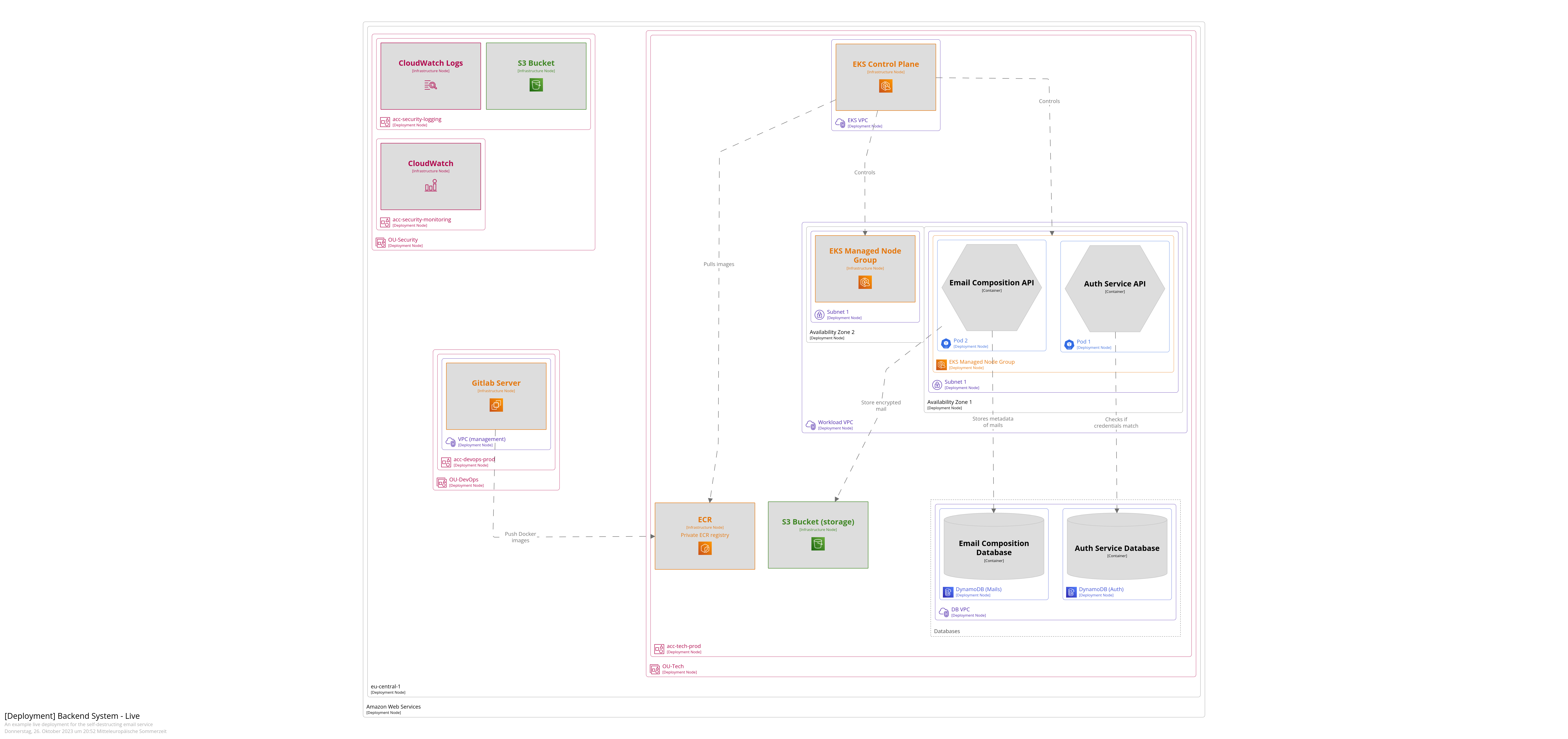
Deployment Live #
The Deployment View in Structurizr is a type of view that visualizes the mapping of software building blocks (like Containers or Components) to infrastructure elements, including servers, containers or cloud services. It gives a clear indication of how and where the software system runs in different environments (like development, staging, production).
|
|
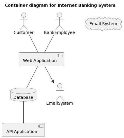
Containers #
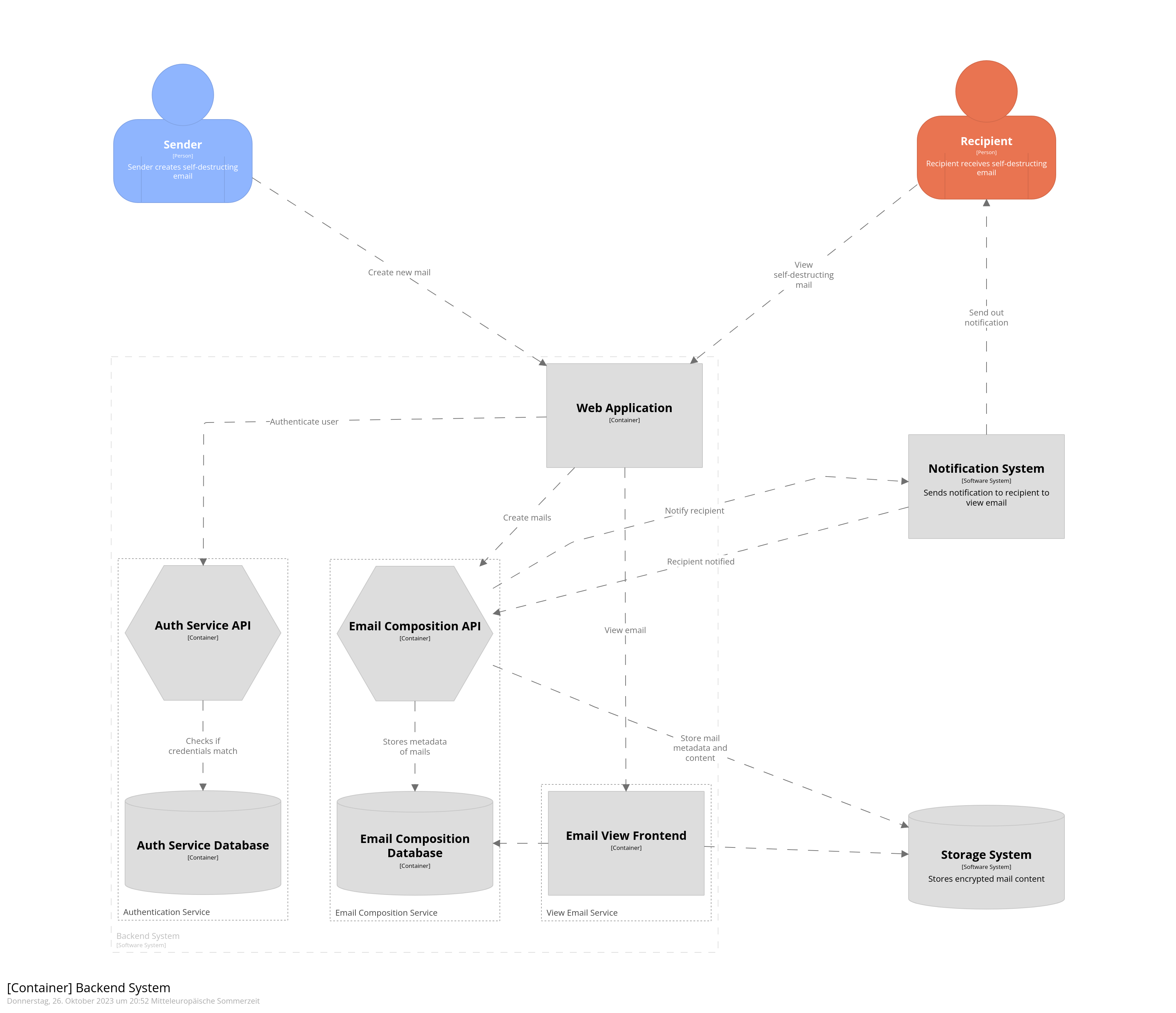
In Structurizr, a Container represents an executable unit (application, data store, microservice, etc.) that encapsulates a portion of your software system. Containers run inside software systems and have interfaces that let them interact with other containers and/or software systems. The Container view shows the internal layout of a software system, specifying contained components and their interactions. This level of abstraction is valuable for developers and others dealing with system implementation and operation.
|
|
And now for specific services:
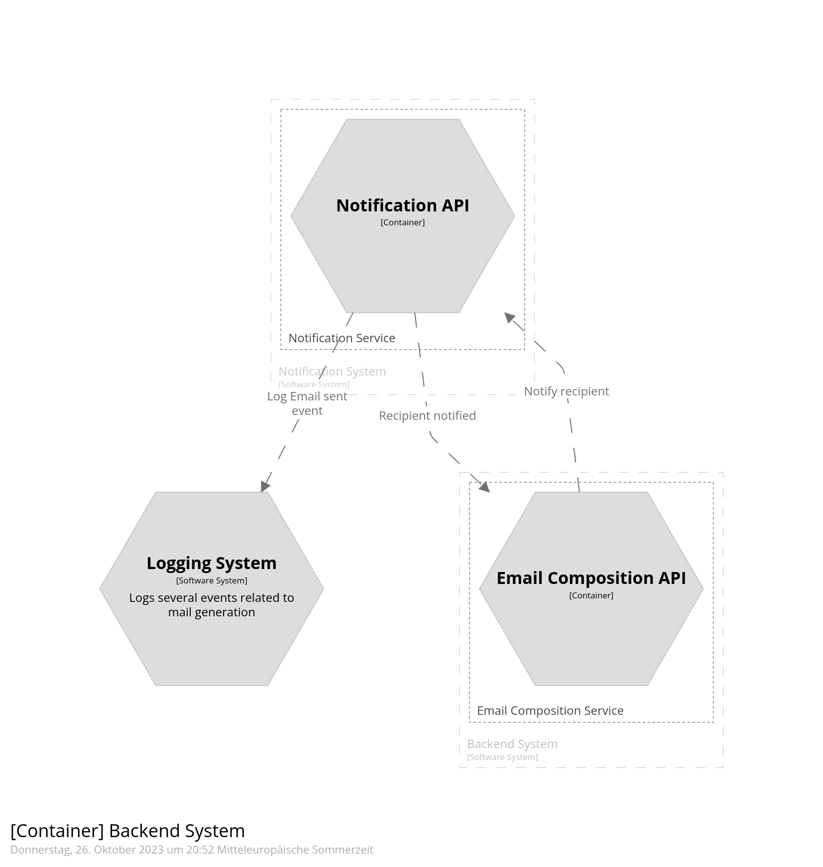
-
Notification Service
1 2 3 4container backend "Containers_NotificationService" { include ->notificationService-> autolayout }Code Snippet 16: Container view for the notification service
-
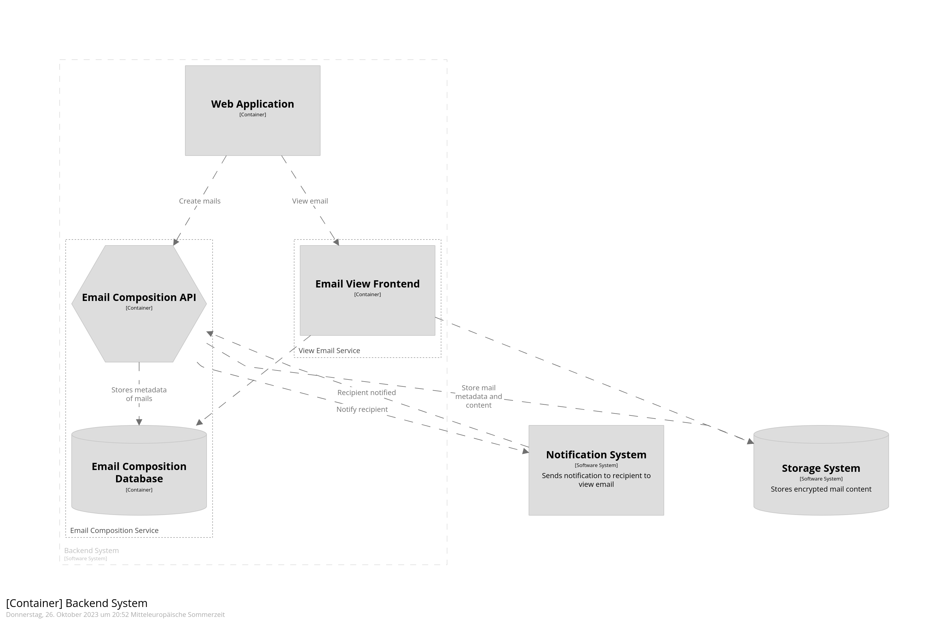
Mail Composition Service
1
2
3
4
container backend "Containers_MailCompositionService" { include ->mailCompositionService-> autolayout }Code Snippet 17: Container view for the email composition service
-
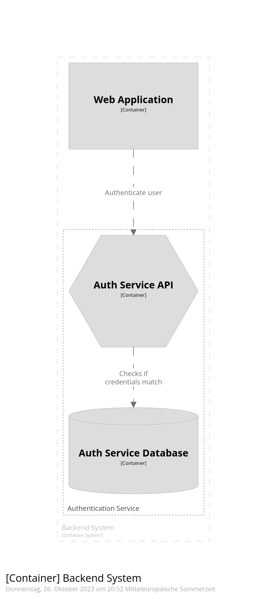
Authentication Service
1
2
3
4
container backend "Containers_AuthenticationService" { include ->authService-> autolayout }Code Snippet 18: Container view for the authentication service
Extra features #
With the online version of Structurizr you get access to diffeerent exporting features:
- PlantUML: Export your model as PlantUML diagrams.
- C4-PlantUML: Export your model as C4-PlantUML diagrams.
- Mermaid: Generate Mermaid diagrams from your model.
- DOT: Export containers and components as DOT graph description language.
- ilograph: Export the model and the views for ilograph.com
Among these I’ve found ilograph to be the most interactive one.
Ilograph #
Once you’ve exported your workspace in ilograph format, follow these steps:
- Create a new ilograph diagram
- Paste in the exported ilograph code
And this is what you get:
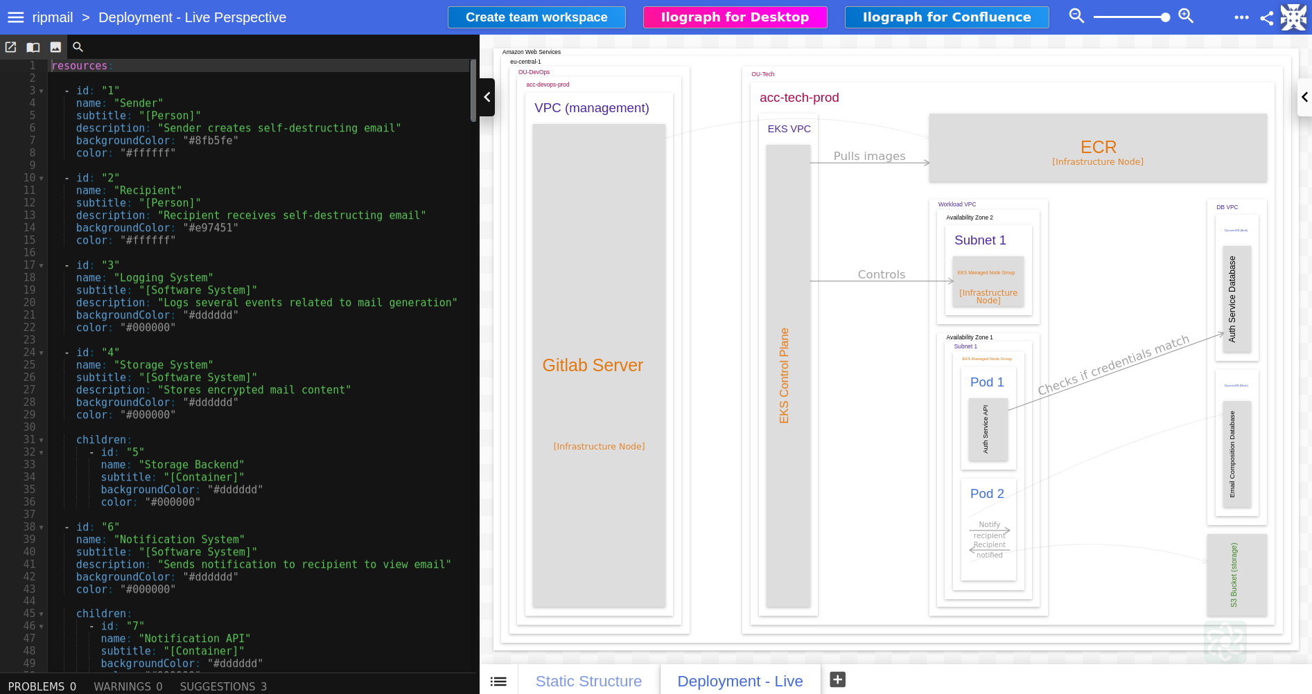
- 👉 Here’s the ilograph code.
- 👉 Check out other architecture diagrams made with ilograph.
Resources #
The resources I’ve consumed for generating the content and diagrams for this blog post:
Tools:
-
2023-10-05 ◦ IcePanel.io
A visual modelling tool for C4
-
2023-10-05 ◦ C4-PlantUML
C4-PlantUML combines the benefits of PlantUML and the C4 model for providing a simple way of describing and communicate software architectures
Articles:
- 2023-10-08 ◦ Software Diagrams - C4 Models with Structurizr
- 2023-07-10 ◦ Structurizr - Practicalli Engineering Playbook
- 2022-10-31 ◦ C4 model for system architecture design
- 2022-10-10 ◦ C4 Models: Architecture From Simple To Complex
Structurizr:
- 2023-10-07 ◦ Structurizr - Help - Themes
Videos:
Outlook #
In the next post I’ll deep-dive into the D2 language which also has a huge set of features. Stay tuned.
This article is part of a series.
- Part 1: Documentation as Code for Cloud
- Part 2: Documentation as Code for Cloud - PlantUML
- Part 3: This Article