As a pseudo-preparation for my CCNA exam I wanted to sum up some of the basic configuration steps related to Cisco switches. Although I won’t handle every topic related to Layer 2, I will assume you have already some network knowledge. The main reason for this post is to show how to setup a really small network infrastructure and configure its components. For my purposes I have used Cisco’s Packet Tracer to simulate the network which I highly recommend. I know there is sth like GNS3 but I didn’t have (yet) the time to look at it.
 1
 2
 3
 4
 5
 6
 7
 8
 9
10
|
%%blockdiag
# <!-- collapse=True -->
diagram admin {
    SW1 [shape = "cisco.layer_2_remote_switch"];
    SW2 [shape = "cisco.layer_2_remote_switch"];
    SW3 [shape = "cisco.layer_2_remote_switch"];

    SW1 <-> SW2;
    SW2 <-> SW3;
}
|

We’ll have 3 switches connected to each other: SW1, SW2 and SW3. Each of these switches (Cisco Catalyst 2960 series) will have one or several VLANs assigned. But first let’s do some house keeping and configure each switch properly. For every switch I’ll do:
- Restrict access
- Add local user
- Set passwords for user
- Restrict console access
- Enable SSH v2
- Allow VTYs to use only SSH
- Disable autologout functionality
- Setup proper console logging
- …
Basic switch configuration
#
1
2
3
4
5
6
7
8
|
Switch>enable
Switch#conf t
Enter configuration commands, one per line.  End with CNTL/Z.
Switch(config)#hostname SW1
SW1(config)#no ip domain-lookup
SW1(config)#service password-encryption
SW1(config)#enable secret admin!
SW1(config)#exit
|
1
2
3
4
|
SW1(config)#line console 0
SW1(config-line)#exec-timeout 0 0
SW1(config-line)#logging synchronous
SW1(config)#exit
|
- Virtual terminal settings:
1
2
3
|
SW1(config)#line vty 0 15
SW1(config-line)#exec-timeout 0 0
SW1(config)#exit
|
 1
 2
 3
 4
 5
 6
 7
 8
 9
10
|
SW1(config)#ip domain-name sw1.local
SW1(config)#crypto key generate rsa
The name for the keys will be: SW1.sw1.local
Choose the size of the key modulus in the range of 360 to 2048 for your
  General Purpose Keys. Choosing a key modulus greater than 512 may take
  a few minutes.

How many bits in the modulus [512]: 2048
% Generating 2048 bit RSA keys, keys will be non-exportable...[OK]
SW1(config)#ip ssh version 2
|
1
2
3
4
|
SW1(config)#line vty 0 15
SW1(config-line)#login local
SW1(config-line)#transport input ssh
SW1(config-line)#exit
|
1
|
SW1(config)#username admin password admin!
|
1
2
3
|
SW1#show ssh
%No SSHv2 server connections running.
%No SSHv1 server connections running.
|
And now store the configuration by replacing the startup-config by the running-config:
1
2
3
|
SW1#copy running-config startup-config
Destination filename [startup-config]?
Building configuration...
|
Now we will apply the same configuration (with slightly different modifications) to SW2 and SW3.
Let’s have a look at the next step and how our small network should look like:
 1
 2
 3
 4
 5
 6
 7
 8
 9
10
11
12
13
14
15
16
17
18
19
20
21
22
23
24
25
26
27
28
29
30
31
32
33
34
35
36
37
38
|
%%blockdiag
# <!-- collapse=True -->
diagram admin {
    SW1 [shape = "cisco.layer_2_remote_switch"];
    SW2 [shape = "cisco.layer_2_remote_switch"];
    SW3 [shape = "cisco.layer_2_remote_switch"];

    PC1 [shape = "cisco.pc"];
    PC2 [shape = "cisco.pc"];
    PC3 [shape = "cisco.pc"];
    PC4 [shape = "cisco.pc"];
    PC5 [shape = "cisco.pc"];
    PC6 [shape = "cisco.pc"];

    SW1 <-> SW2 [label = "F0/1   -   F0/1"];
    SW2 <-> SW3 [label = "F0/2   -   F0/1"];

    group {
        orientation = portrait;
        color = "#FFF";
        SW1 <-> PC1 [label = "F0/2 - F0"];
        SW1 <-> PC2 [label = "F0/3 - F0"];
    }

    group {
        orientation = portrait;
        color = "#FFF";
        SW2 <-> PC3 [label = "F0/3 - F0"];
        SW2 <-> PC4 [label = "F0/4 - F0"];
    }

    group {
        orientation = portrait;
        color = "#FFF";
        SW3 <-> PC5 [label = "F0/3 - F0"];
        SW3 <-> PC6 [label = "F0/4 - F0"];
    }
}
|
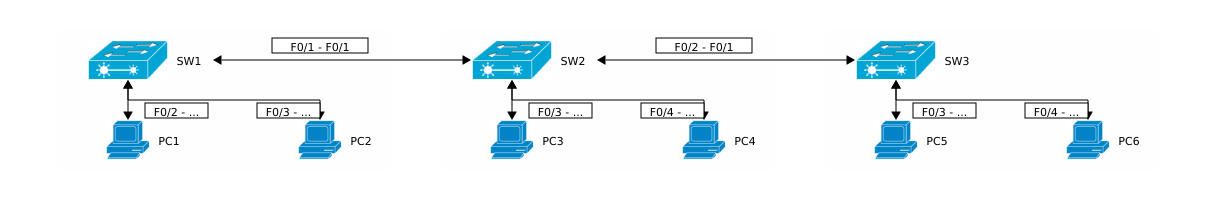
Following table shows the links between the switches and the PCs and which switch ports are being used:
| PC |
SW1 |
SW2 |
SW3 |
| PC1 |
F0/2 |
|
|
| PC2 |
F0/3 |
|
|
| PC3 |
|
F0/3 |
|
| PC4 |
|
F0/4 |
|
| PC5 |
|
|
F0/3 |
| PC6 |
|
|
F0/4 |
Now I’ll configure the ports on between SW1 and SW2:
- Set duplex and link speed:
1
2
3
4
5
6
|
SW1#conf t
SW1(config)#int f0/1
SW1(config-if)#dupl
SW1(config-if)#duplex full
SW1(config-if)#speed 100
SW1(config-if)#description SW2 connects here
|
1
2
3
4
|
SW1(config-if)#switchport mode trunk
SW1(config-if)#switchport trunk encapsulation dot1q
SW1(config-if)#no shhutdown
SW1(config-if)#end
|
- Check switchport configuration:
 1
 2
 3
 4
 5
 6
 7
 8
 9
10
11
12
|
SW1#sh int f0/1 switchport
Name: Fa0/1
Switchport: Enabled
Administrative Mode: trunk
Operational Mode: down
Administrative Trunking Encapsulation: dot1q
Operational Trunking Encapsulation: dot1q
Negotiation of Trunking: On
Access Mode VLAN: 1 (default)
Trunking Native Mode VLAN: 1 (default)
Voice VLAN: none
...
|
- Check interface configuration:
 1
 2
 3
 4
 5
 6
 7
 8
 9
10
11
|
SW1#sh int f0/1
FastEthernet0/1 is down, line protocol is down (disabled)
  Hardware is Lance, address is 0090.211e.2e01 (bia 0090.211e.2e01)
  Description: Sw2 connects here
 BW 100000 Kbit, DLY 1000 usec,
     reliability 255/255, txload 1/255, rxload 1/255
  Encapsulation ARPA, loopback not set
  Keepalive set (10 sec)
  Full-duplex, 100Mb/s
  input flow-control is off, output flow-control is off
...
|
You should have noticed that the interfaces is currently down. This happens due to encapsulation misconfiguration between the two switches. After having SW2 configured as well you should have:
 1
 2
 3
 4
 5
 6
 7
 8
 9
10
11
12
13
14
15
16
17
18
19
20
21
22
23
|
SW2#sh int f0/1 switchport
Name: Fa0/1
Switchport: Enabled
Administrative Mode: trunk
Operational Mode: trunk
Administrative Trunking Encapsulation: dot1q
Operational Trunking Encapsulation: dot1q
Negotiation of Trunking: On
Access Mode VLAN: 1 (default)
Trunking Native Mode VLAN: 1 (default)
Voice VLAN: none
...

SW2#sh int f0/1
FastEthernet0/1 is up, line protocol is up (connected)
  Hardware is Lance, address is 00d0.58ac.4d01 (bia 00d0.58ac.4d01)
  Description: SW1 connects here
 BW 100000 Kbit, DLY 1000 usec,
     reliability 255/255, txload 1/255, rxload 1/255
  Encapsulation ARPA, loopback not set
  Keepalive set (10 sec)
  Full-duplex, 100Mb/s
...
|
Now we should have a working trunk between SW1 and SW2. The link between Sw2 and Sw3 should be then configured as well.
Add VLANs
#
Now I’ll create 2 VLANs:
- VLAN Students
- ID: 10
- Network address:
10.10.10.0/24
- Hosts:
PC1, PC2, PC5
- VLAN Teachers
- ID: 20
- Network address:
20.20.20.0/24
- Hosts:
PC3, PC4, PC6
Additionally every host PC gets following IP addresss:
| Host |
IP |
VLAN |
| PC1 |
10.10.10.101 |
Students |
| PC2 |
10.10.10.102 |
Students |
| PC3 |
20.20.20.103 |
Teachers |
| PC4 |
20.20.20.104 |
Teachers |
| PC5 |
10.10.10.105 |
Students |
| PC6 |
20.20.20.106 |
Teachers |
Now let’s have a look at our topology:
 1
 2
 3
 4
 5
 6
 7
 8
 9
10
11
12
13
14
15
16
17
18
19
20
21
22
23
24
25
26
27
28
29
30
31
32
33
34
35
36
37
38
39
40
41
|
%%blockdiag
# <!-- collapse=True -->
diagram admin {
    SW1 [shape = "cisco.layer_2_remote_switch"];
    SW2 [shape = "cisco.layer_2_remote_switch"];
    SW3 [shape = "cisco.layer_2_remote_switch"];

    PC1 [shape = "cisco.pc"];
    PC2 [shape = "cisco.pc"];
    PC3 [shape = "cisco.pc"];
    PC4 [shape = "cisco.pc"];
    PC5 [shape = "cisco.pc"];
    PC6 [shape = "cisco.pc"];

    SW1 <-> SW2;
    SW2 <-> SW3;

    group {
        orientation = portrait;
        label = "VLAN 10";
        color = "#FFF000";
        SW1 <-> PC1;
        SW1 <-> PC2;
    }

    group {
        orientation = portrait;
        label = "VLAN 20";
        color = "#FFFEEE";
        SW2 <-> PC3;
        SW2 <-> PC4;
    }

    group {
        orientation = portrait;
        label = "VLAN 10 + VLAN 20";
        color = "#FFFDDD";
        SW3 <-> PC5;
        SW3 <-> PC6;
    }
}
|
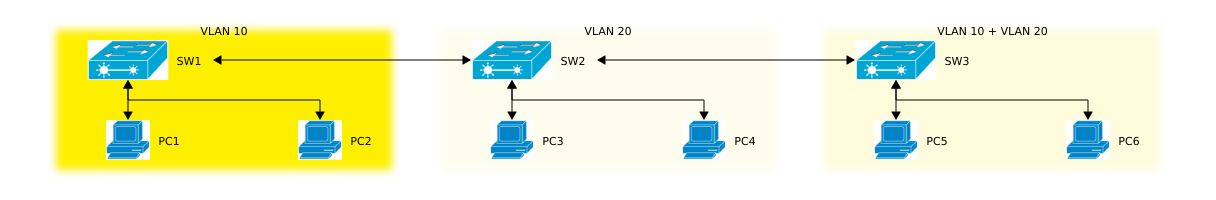
Keep in mind that the switches don’t really belong to any VLANs at all.
Add VLAN Students
#
Adding the VLAN configuration has to be done on every switch. I could have used VTP (VLAN Trunking Protocol) but for the sake of exercise I’ll do it manually, beginning with SW1:
1
2
3
4
5
6
7
|
SW1(config)#vlan 10
SW1(config-vlan)#name Students
SW1(config-vlan)#exit
SW1(config)#int range f0/2 - 3
SW1(config-if-range)#switchport mode access
SW1(config-if-range)#switchport access vlan 10
SW1(config-if-range)#no shutdown
|
Now do the same with SW3 (ports are of course different):
1
2
3
4
|
SW3(config)#int f0/3
SW3(config-if)#switchport mode access
SW3(config-if)#switchport access vlan 10
SW3(config-if)#no shutdown
|
Add the VLAN config to SW2 as well:
1
2
3
|
SW2(config)#vlan 10
SW2(config-vlan)#name Students
SW2(config-vlan)#exit
|
Add VLAN Teachers
#
The configuration is pretty straight-forward:
1
2
3
4
5
6
7
|
SW2(config)#vlan 20
SW2(config-vlan)#name Teachers
SW2(config-vlan)#exit
SW2(config)#int range f0/3 - 4
SW2(config-if-range)#switchport mode access
SW2(config-if-range)#switchport access vlan 10
SW2(config-if-range)#no shutdown
|
Now on SW3:
1
2
3
4
5
6
|
SW3(config-vlan)#name Teachers
SW3(config-vlan)#exit
SW3(config)#int f0/2
SW3(config-if)#switchport mode access
SW3(config-if)#switchport access vlan 20
SW3(config-if)#no shutdown
|
Don’t forget to add the VLAN config to SW1 as well:
1
2
3
|
SW1(config)#vlan 20
SW1(config-vlan)#name Teachers
SW1(config-vlan)#exit
|
Restrict VLANs on trunk ports
#
If you have a look at the configured trunk ports, you’ll get sth like this:
 1
 2
 3
 4
 5
 6
 7
 8
 9
10
11
12
|
SW1#sh int trunk
Port        Mode         Encapsulation  Status        Native vlan
Fa0/1       on           802.1q         trunking      1

Port        Vlans allowed on trunk
Fa0/1       1-1005

Port        Vlans allowed and active in management domain
Fa0/1       1,10,20

Port        Vlans in spanning tree forwarding state and not pruned
Fa0/1       1,10,20
|
You’ll notice that the allowed VLANs on the trunk ports range from 1-1005. Actually (and due to security reasons) we want to restrict the VLANs which should be forwarded by the switches:
1
2
|
SW1(config)#int f0/1
SW1(config-if)#switchport trunk allowed vlan 10,20
|
We only want to allow frames with a VLAN tag id = {10, 20}. Every trunk port must be configured that way. Finally you can verify that by:
 1
 2
 3
 4
 5
 6
 7
 8
 9
10
11
12
13
14
15
16
|
SW2#sh int trunk
Port        Mode         Encapsulation  Status        Native vlan
Fa0/1       on           802.1q         trunking      1
Fa0/2       on           802.1q         trunking      1

Port        Vlans allowed on trunk
Fa0/1       10,20
Fa0/2       10,20

Port        Vlans allowed and active in management domain
Fa0/1       10,20
Fa0/2       10,20

Port        Vlans in spanning tree forwarding state and not pruned
Fa0/1       10,20
Fa0/2       10,20
|
Traditionally switches operate on Layer 2. By using SVIs (Switch Virtual Interface) the switches uses a virtual Layer 3 interface to route traffic to other Layer 3 interface without any physical router. VLANs divide networks into smaller segments which keep traffic inside the VLAN. And because each VLAN has its own domain, a mechanism is needed to pass data to other VLANs.
In our case we’ll have to add each switch to some VLAN and assign some SVI a valid routable IP address.
| Switch |
IP address |
VLAN |
| SW1 |
30.30.30.1 |
Management |
| SW2 |
30.30.30.2 |
Management |
| SW3 |
30.30.30.3 |
Management |
 1
 2
 3
 4
 5
 6
 7
 8
 9
10
11
|
SW1(config)#vlan 30
SW1(config-vlan)#name Management
SW1(config-vlan)#exit
SW1(config)#int vlan 30
SW1(config-if)#
%LINK-5-CHANGED: Interface Vlan30, changed state to up

SW1(config-if)#ip address 30.30.30.1 255.255.255.0
SW1#sh ip int brief
...
Vlan30                 30.30.30.1      YES manual up                    down
|
 1
 2
 3
 4
 5
 6
 7
 8
 9
10
11
12
|
SW2(config)#vlan 30
SW2(config-vlan)#name Management
SW2(config-vlan)#exit
SW2(config)#int vlan 30
SW2(config-if)#
%LINK-5-CHANGED: Interface Vlan30, changed state to up

SW2(config-if)#ip add
SW2(config-if)#ip address 30.30.30.2 255.255.255.0
SW2#sh ip int brief
...
Vlan30                 30.30.30.2      YES manual up                    down
|
 1
 2
 3
 4
 5
 6
 7
 8
 9
10
11
|
SW3(config)#vlan 30
SW3(config-vlan)#name Management
SW3(config-vlan)#exit
SW3(config)#int vlan 30
SW3(config-if)#
%LINK-5-CHANGED: Interface Vlan30, changed state to up

SW3(config-if)#ip address 30.30.30.3 255.255.255.0
SW3#sh ip int brief
...
Vlan30                 30.30.30.3      YES manual up                    down
|
As you can see the interfaces are all in up/down state which is generally a Layer 2 problem. If you remember correctly we have configured the trunk ports previously. We also allowed only specific VLANs to pass through these trunks. In this case we’ll have to allow VLAN Management as well. Just an example for SW2:
1
2
|
SW2(config)#int range f0/1 - 2
SW2(config-if-range)#switchport trunk allowed vlan 10,20,30
|
Now the port should be resetted:
1
2
3
4
5
6
7
|
SW2(config)#int vlan 30
SW2(config-if)#no shutdown
SW2(config-if)#
%LINEPROTO-5-UPDOWN: Line protocol on Interface Vlan30, changed state to up

SW2(config-if)#^Z
|
And then check again the port state:
1
2
3
|
SW2#sh ip int brief
...
Vlan30                 30.30.30.2      YES manual up                    up
|
The configuration steps for SW1 and SW3 are here intentionally ommitted.
Connectivity
#
Ping between PCs
#
Now let’s check the connectivity between the posts:
 1
 2
 3
 4
 5
 6
 7
 8
 9
10
11
12
13
|
PC>ping 10.10.10.102

Pinging 10.10.10.102 with 32 bytes of data:

Reply from 10.10.10.102: bytes=32 time=1ms TTL=128
Reply from 10.10.10.102: bytes=32 time=0ms TTL=128
Reply from 10.10.10.102: bytes=32 time=0ms TTL=128
Reply from 10.10.10.102: bytes=32 time=0ms TTL=128

Ping statistics for 10.10.10.102:
    Packets: Sent = 4, Received = 4, Lost = 0 (0% loss),
Approximate round trip times in milli-seconds:
    Minimum = 0ms, Maximum = 1ms, Average = 0ms
|
 1
 2
 3
 4
 5
 6
 7
 8
 9
10
11
12
13
|
PC>ping 10.10.10.105

Pinging 10.10.10.105 with 32 bytes of data:

Reply from 10.10.10.105: bytes=32 time=1ms TTL=128
Reply from 10.10.10.105: bytes=32 time=0ms TTL=128
Reply from 10.10.10.105: bytes=32 time=0ms TTL=128
Reply from 10.10.10.105: bytes=32 time=0ms TTL=128

Ping statistics for 10.10.10.105:
    Packets: Sent = 4, Received = 4, Lost = 0 (0% loss),
Approximate round trip times in milli-seconds:
    Minimum = 0ms, Maximum = 1ms, Average = 0ms
|
 1
 2
 3
 4
 5
 6
 7
 8
 9
10
11
12
13
|
PC>ping 20.20.20.106

Pinging 20.20.20.106 with 32 bytes of data:

Reply from 20.20.20.106: bytes=32 time=0ms TTL=128
Reply from 20.20.20.106: bytes=32 time=0ms TTL=128
Reply from 20.20.20.106: bytes=32 time=0ms TTL=128
Reply from 20.20.20.106: bytes=32 time=0ms TTL=128

Ping statistics for 20.20.20.106:
    Packets: Sent = 4, Received = 4, Lost = 0 (0% loss),
Approximate round trip times in milli-seconds:
    Minimum = 0ms, Maximum = 0ms, Average = 0ms
|
Ping between Switches
#
1
2
3
4
5
6
|
SW3#ping 30.30.30.1

Type escape sequence to abort.
Sending 5, 100-byte ICMP Echos to 30.30.30.1, timeout is 2 seconds:
..!!!
Success rate is 60 percent (3/5), round-trip min/avg/max = 0/0/0 ms
|
The first 2 ICMP Echo Requests were not successful because SW3 and SW2 didn’t have yet the MAC address of SW1. The 2nd ping command will therefore have 100% connectivity rate since the MAC address table has been updated:
1
2
3
4
5
6
|
SW3#ping 30.30.30.1

Type escape sequence to abort.
Sending 5, 100-byte ICMP Echos to 30.30.30.1, timeout is 2 seconds:
!!!!!
Success rate is 100 percent (5/5), round-trip min/avg/max = 0/1/6 ms
|
SSH
#
 1
 2
 3
 4
 5
 6
 7
 8
 9
10
11
12
|
SW1#ssh -l admin -v 2 30.30.30.2
Open
Password:


SW2>enable
Password:
SW2#exit

[Connection to 30.30.30.2 closed by foreign host]
SW1#
|
MAC address tables
#
Now that we have pinged the hosts, the switches should now have all MAC addresses in their tables:
 1
 2
 3
 4
 5
 6
 7
 8
 9
10
11
12
13
14
15
|
SW2#show mac address-table
          Mac Address Table
-------------------------------------------

Vlan    Mac Address       Type        Ports
----    -----------       --------    -----

   1    0030.a341.e901    DYNAMIC     Fa0/2
   1    0090.211e.2e01    DYNAMIC     Fa0/1
  10    0001.437b.a40c    DYNAMIC     Fa0/2
  10    0030.a341.e901    DYNAMIC     Fa0/2
  10    0030.f28c.c65a    DYNAMIC     Fa0/1
  20    0030.a319.da0b    DYNAMIC     Fa0/4
  20    0030.a341.e901    DYNAMIC     Fa0/2
  20    0060.7079.8692    DYNAMIC     Fa0/2
|
Security
#
Port security
#
Now suppose SW1 should implement port security and therefore allow only pre-defined devices to connect to the switch. This will prevent devices which MAC addresses is not included in the whitelist from sending frames through SW1. The next commands will configure port security for ports F0/2 (PC1) and F0/3 (PC2):
 1
 2
 3
 4
 5
 6
 7
 8
 9
10
|
SW1#conf t
Enter configuration commands, one per line.  End with CNTL/Z.
SW1(config)#int f0/2
SW1(config-if)#switchport port-security
SW1(config-if)#switchport port-security mac-address 0030.f28c.c65a
SW1(config-if)#exit
SW1(config)#int f0/3
SW1(config-if)#switchport port-security
SW1(config-if)#switchport port-security mac-address 0060.2fd2.a80a
SW1(config-if)#exit
|
Check the configuration:
 1
 2
 3
 4
 5
 6
 7
 8
 9
10
11
12
13
14
15
16
17
18
19
20
21
22
23
24
25
26
27
|
SW1#sh port-security int f0/2
Port Security              : Enabled
Port Status                : Secure-up
Violation Mode             : Shutdown
Aging Time                 : 0 mins
Aging Type                 : Absolute
SecureStatic Address Aging : Disabled
Maximum MAC Addresses      : 1
Total MAC Addresses        : 1
Configured MAC Addresses   : 1
Sticky MAC Addresses       : 0
Last Source Address:Vlan   : 0030.F28C.C65A:10
Security Violation Count   : 0

SW1#sh port-security int f0/3
Port Security              : Enabled
Port Status                : Secure-up
Violation Mode             : Shutdown
Aging Time                 : 0 mins
Aging Type                 : Absolute
SecureStatic Address Aging : Disabled
Maximum MAC Addresses      : 1
Total MAC Addresses        : 1
Configured MAC Addresses   : 0
Sticky MAC Addresses       : 0
Last Source Address:Vlan   : 0060.2FD2.A80A:10
Security Violation Count   : 0
|