This article is part of a series.
- Part 1: Documentation as Code for Cloud
- Part 2: This Article
- Part 3: Documentation as Code for Cloud - C4 Model & Structurizr
Basics #
I’ve become a huge fan of PlantUML even before I came across the concept of “documentation as code” I also code for presentations. So the term presentation as code is also a thing. and it instantly won me over with its capabilities. I have used it in many different roles (software engineer, security engineer, security architect) extensively to draw diagrams (components, sequences) and mind maps.
Though initially, the general syntax might seem a bit challenging to understand, I believe that with some dedication, the learning curve becomes quite manageable. The reward of mastering PlantUML is well worth the effort, as it empowers you to create visually engaging and informative diagrams seamlessly.
One aspect where PlantUML might fall short is its default styling, which may not be as visually impressive as some other tools. However, this drawback can easily be overcome by incorporating icons and leveraging different themes to breathe life into your diagrams. For really cool diagrams you might want to have a look at PlantUML Hitchhikers Guide. By doing so, you can elevate the aesthetic appeal and overall quality of your visual representations significantly by using standard icons (included withing the standard library) and 3rd-party ones .
Let’s have a look how how a typical PlantUML document could look like:
|
|
At the top of the document ❶ you define the basic layout of the resulting drawing (landscape mode, font size, font family, default direction in which resources should be created, etc.). Then you start adding different modules ❷ and ➌ which provide different entities and icons based on your needs. Finally you use your resources/entities, arrange them correspondingly and make relationships between them ❹.
This is what I’ll use for the examples within this blog post:
In this example I’ve cloned aws-icons-for-plantuml locally. That’s why I’ve used
/home/victor/work/repos/aws-icons-for-plantuml/dist as the location of the AWS
icon distribution. But you can still use an external URL such as
https://raw.githubusercontent.com/awslabs/aws-icons-for-plantuml/v16.0/dist.
|
|
PlantUML is a powerful tool that goes beyond just creating basic diagrams; it also supports various types of grouped areas. These groupings play a crucial role in emphasizing the logical connections between different components or resources that belong to the same category, making it easier to understand complex systems.
When working with PlantUML, you have the flexibility to employ different types of groups to organize your diagrams effectively. Some of these groups include:
| Group name | Description |
|---|---|
| GenericGroup | If the predefined groups don’t suit your needs, you can use this group type for custom arrangements. |
| GenericAltGroup | Similar to the generic group, this one allows for alternative custom groupings. |
| AWSCloudAltGroup | This group allows you to represent alternative cloud arrangements in your AWS diagrams. |
| VPCGroup | It lets you create a clear representation of components within an AWS Virtual Private Cloud. |
| RegionGroup | It enables you to logically group components based on AWS regions. |
| AvailabilityZoneGroup | With this group, you can highlight components grouped by availability zones in AWS. |
| SecurityGroupGroup | Use this group to demonstrate the logical connections between security groups in AWS. |
| AutoScalingGroupGroup | This group is perfect for showcasing auto-scaling groups and their relationships. |
| PrivateSubnetGroup | This group emphasizes components that are part of private subnets in AWS. |
| PublicSubnetGroup | Similar to the previous one, but for components in public subnets in AWS. |
| ServerContentsGroup | Use this group to illustrate the contents of a server or its internal |
| CorporateDataCenterGroup | It helps you highlight components within a corporate data center. |
| EC2InstanceContentsGroup | Use this group to show the internal structure or contents of an EC2 instance. |
| SpotFleetGroup | This group allows you to group instances in AWS Spot Fleet. |
| AWSAccountGroup | With this group, you can demonstrate various components within an AWS account. |
| IoTGreengrassDeploymentGroup | Use this group to illustrate deployments in AWS IoT Greengrass. |
| IoTGreengrassGroup | This group lets you represent components within AWS IoT Greengrass. |
| ElasticBeanstalkContainerGroup | Use this group to showcase container-related elements in AWS Elastic Beanstalk. |
| StepFunctionsWorkflowGroup | This group is perfect for visually representing AWS Step Functions workflows. |
Groups #
Let’s have a look at the most common groups:
-
Generic group
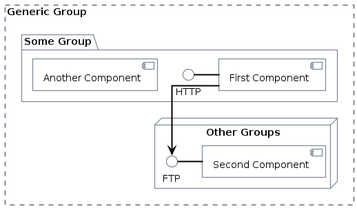
The most useful group (without any icons) is the generic group:
1 2 3 4 5 6 7 8 9 10 11GenericGroup(generic_group, "Generic Group") { package "Some Group" { HTTP - [First Component] [Another Component] } node "Other Groups" { FTP - [Second Component] [First Component] --> FTP } }Code Snippet 2: Using generic group
-
Generic alt group
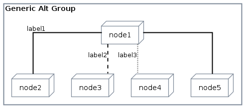
If you want to use another layout (without dotted lines) you could go for generic alt group:
1 2 3 4 5 6 7 8 9 10 11GenericAltGroup(generic_alt_group, "Generic Alt Group") { node node1 node node2 node node3 node node4 node node5 node1 -- node2 : label1 node1 .. node3 : label2 node1 ~~ node4 : label3 node1 == node5 }Code Snippet 3: Using generic alt group👉 Full PlantUML Code
-
AWS Cloud Group
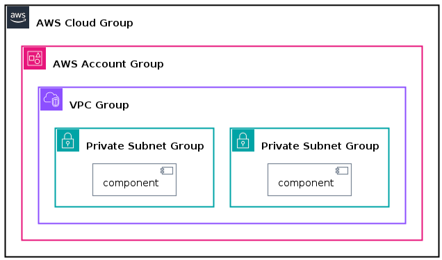
The AWSCloudGroup along with AWSAccountGroup provides a more AWS-like grouping of resources. Here is one example using VPCs and private subnets:
1 2 3 4 5 6 7 8 9 10 11 12AWSCloudGroup(aws_cloud, "AWS Cloud Group") { AWSAccountGroup(aws_acc_group, "AWS Account Group") { VPCGroup(vpc_group, "VPC Group") { PrivateSubnetGroup(priv_subnet1, "Private Subnet Group") { [component] as C1 } PrivateSubnetGroup(priv_subnet2, "Private Subnet Group") { [component] as C2 } } } }Code Snippet 4: Using AWS cloud group👉 Full PlantUML Code
AWS Architecture #
On our journey of designing the AWS architecture for our innovative self-destroying email service, we should begin with a high-level overview to lay down the foundation. With PlantUML at our disposal, it’s a wise approach to start by sketching the fundamental high-level concepts You may also check the first post for some diagrams using pen & paper. before going to deep into details.
By starting with the organizational units and gradually adding layers of complexity, we can systematically build upon the architecture, ensuring a coherent and comprehensive representation of the entire system. This step-by-step approach allows us to understand each component’s role and relationships before moving forward.
In this initial phase, we’ll focus on capturing the essence of the architecture, identifying the main components and their relationships. As we move on, we can gradually introduce additional elements/components to achieve a holistic and detailed representation of the mail service.
Remember, a well-structured high-level design serves as a roadmap, guiding us through the design process and identifying potential challenges or areas that require further refinement. With PlantUML as our visual design tool, we can easily iterate and modify the architecture as needed, ensuring that our self-destroying email service is built on a solid and scalable foundation. So, let’s start with the big picture and refine it step by step to create an AWS architecture that meets our requirements.
Account level #
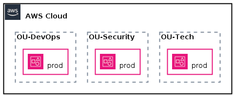
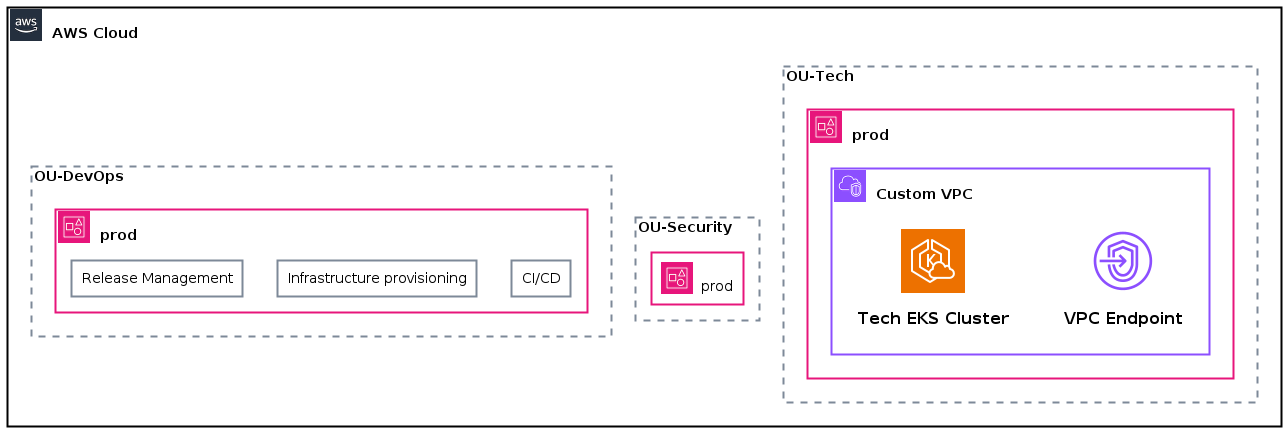
On the organizational level, we have three accounts: OU-Tech, OU-Security, and OU-DevOps. Each account has a prod environment.
|
|
VPCs and responsibilities #
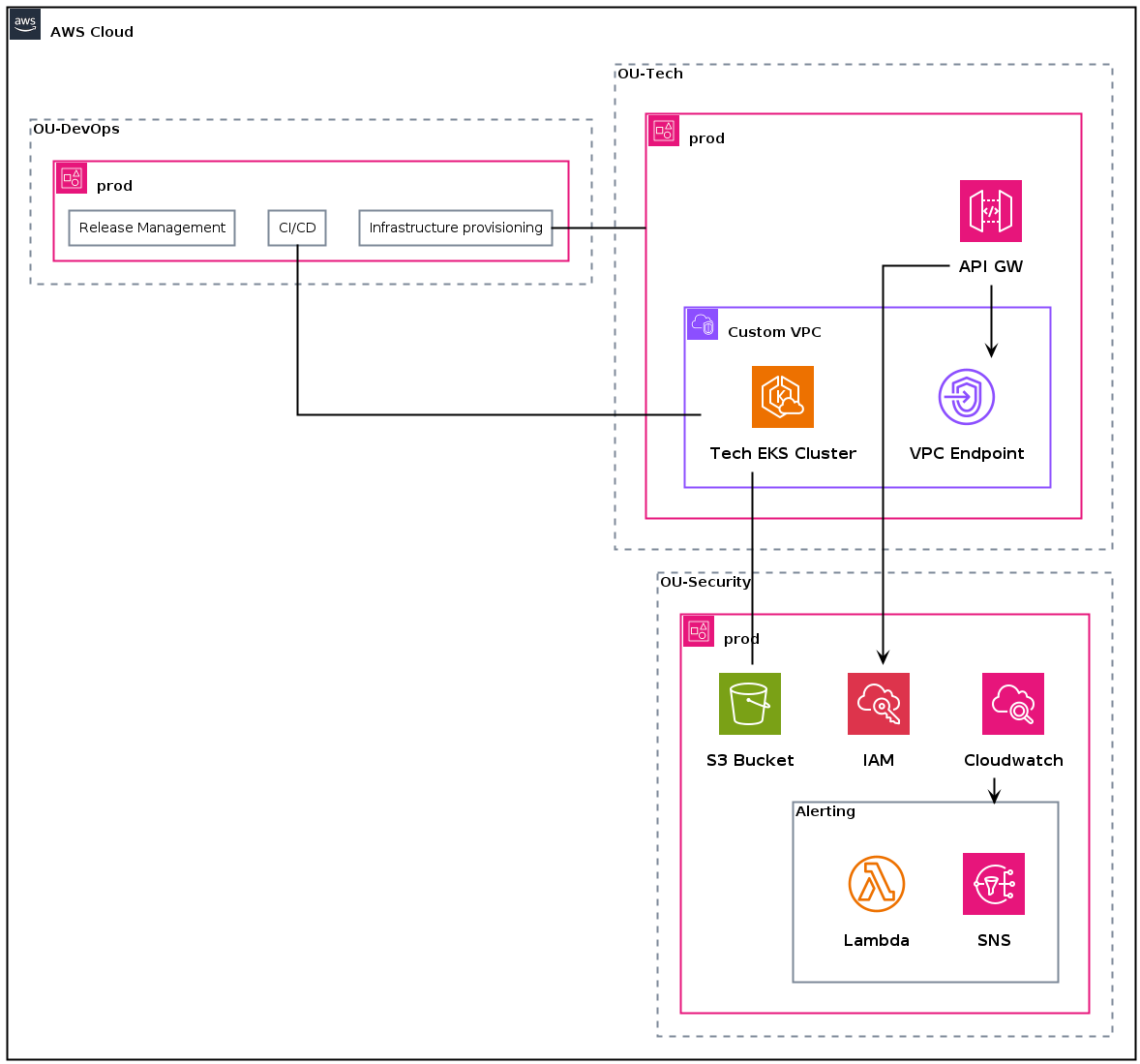
On the VPC level, we have a custom VPC with two private subnets. The VPC has a VPC endpoint to API Gateway. The VPC endpoint is used by the API Gateway to access the EKS cluster.
The DevOps organizational unit also has some responsibilities which are highlighted as “groups” inside the OU.
|
|
Relations #
|
|
What about the rest? #
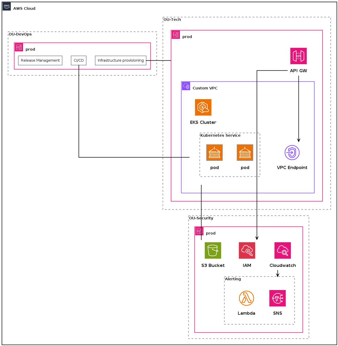
Our diagram is not complete yet. Every group region could have its own diagram (as if you would zoom in into a specific component). Let’s have a look how we add Kubernetes related components such as nodes, pods and services. Also have a look at Hitchhikers Guide on Kubernetes.
|
|
Sequence diagrams #
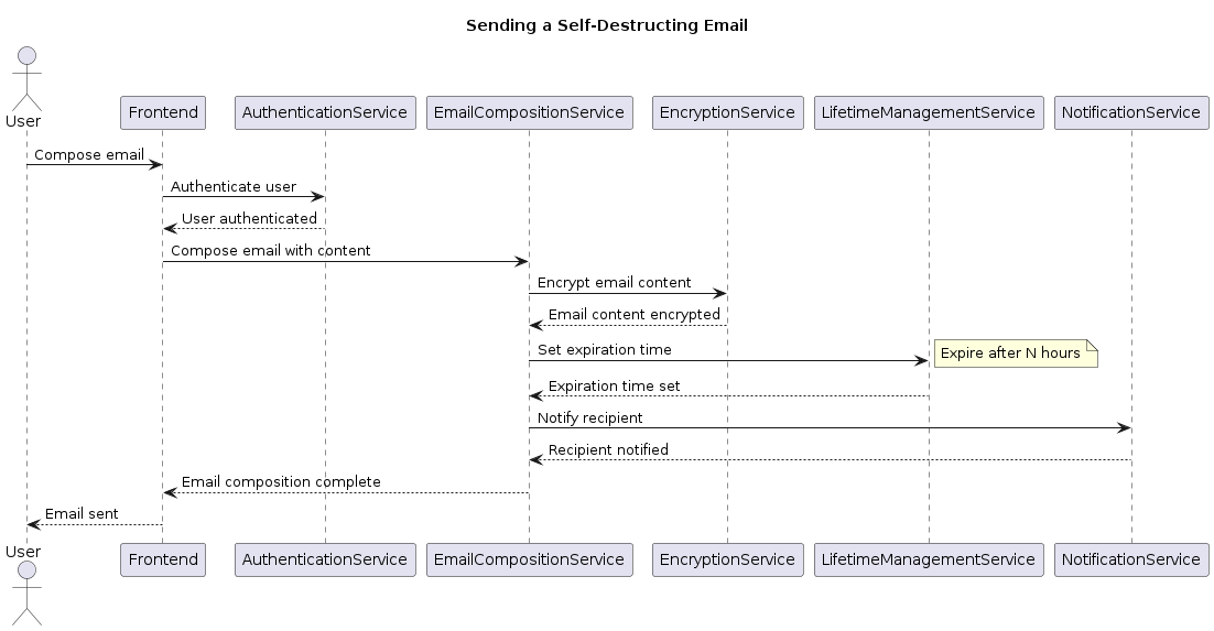
When examining the previsouly sketched architecture, it is not immediately clear how the mail service can be used. To gain a better understanding of the fundamental workflows, it is necessary to adopt sequence diagrams. These diagrams should be created for each business use case.
The examples below don’t require the epilogue (styling and additional modules).
Without fancy icons #
Let’s explore some sequence diagrams without icons and additional styling:
-
Compose and send mails
1 2 3 4 5 6 7 8 9 10 11 12 13 14 15 16 17 18 19 20 21 22 23 24 25@startuml title Sending a Self-Destructing Email actor User participant Frontend participant AuthenticationService participant EmailCompositionService participant EncryptionService participant LifetimeManagementService participant NotificationService User -> Frontend: Compose email Frontend -> AuthenticationService: Authenticate user AuthenticationService --> Frontend: User authenticated Frontend -> EmailCompositionService: Compose email with content EmailCompositionService -> EncryptionService: Encrypt email content EncryptionService --> EmailCompositionService: Email content encrypted EmailCompositionService -> LifetimeManagementService: Set expiration time note right: Expire after N hours LifetimeManagementService --> EmailCompositionService: Expiration time set EmailCompositionService -> NotificationService: Notify recipient NotificationService --> EmailCompositionService: Recipient notified EmailCompositionService --> Frontend: Email composition complete Frontend --> User: Email sent @endumlCode Snippet 9: Plantuml👉 Full PlantUML Code
-
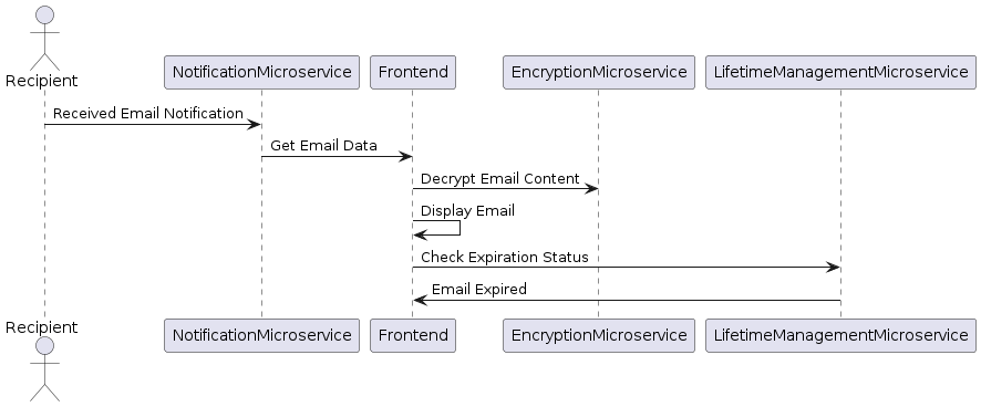
Receive and view mails
1 2 3 4 5 6 7 8 9 10 11 12 13 14@startuml actor Recipient participant NotificationMicroservice participant Frontend participant EncryptionMicroservice participant LifetimeManagementMicroservice Recipient -> NotificationMicroservice: Received Email Notification NotificationMicroservice -> Frontend: Get Email Data Frontend -> EncryptionMicroservice: Decrypt Email Content Frontend -> Frontend: Display Email Frontend -> LifetimeManagementMicroservice: Check Expiration Status LifetimeManagementMicroservice -> Frontend: Email Expired @endumlCode Snippet 10: Plantuml sequence diagram for receiving and viewing mails👉 Full PlantUML Code
-
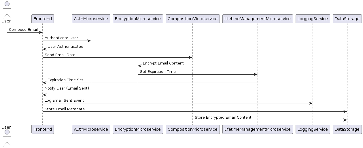
Compose and send mails (with logging)
Now let’s complicate things a little bit and also make sure we log requests and store necessary data to our storage system:
1 2 3 4 5 6 7 8 9 10 11 12 13 14 15 16 17 18 19 20 21 22@startuml actor User participant Frontend participant AuthMicroservice participant EncryptionMicroservice participant CompositionMicroservice participant LifetimeManagementMicroservice participant LoggingService participant DataStorage User -> Frontend: Compose Email Frontend -> AuthMicroservice: Authenticate User AuthMicroservice -> Frontend: User Authenticated Frontend -> CompositionMicroservice: Send Email Data CompositionMicroservice -> EncryptionMicroservice: Encrypt Email Content EncryptionMicroservice -> LifetimeManagementMicroservice: Set Expiration Time LifetimeManagementMicroservice -> Frontend: Expiration Time Set Frontend -> Frontend: Notify User (Email Sent) Frontend -> LoggingService: Log Email Sent Event Frontend -> DataStorage: Store Email Metadata CompositionMicroservice -> DataStorage: Store Encrypted Email Content @endumlCode Snippet 11: Plantuml sequence diagram for composing and sending mails (with logging)👉 Full PlantUML Code
With AWS Icons #
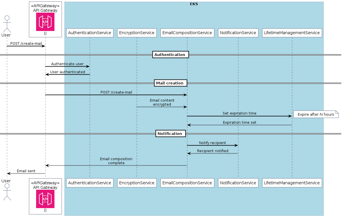
Let’s add some AWS related icons and some boxes (for emphasizing components that belong together):
-
Send mails
1 2 3 4 5 6 7 8 9 10 11 12 13 14 15 16 17 18 19 20 21 22 23 24 25 26 27 28 29 30 31 32 33 34 35 36 37 38 39 40 41 42 43@startuml ' Epilogue skinparam BoxPadding 10 ' !define AWSPuml https://raw.githubusercontent.com/awslabs/aws-icons-for-plantuml/v16.0/dist !define AWSPuml /home/victor/work/repos/aws-icons-for-plantuml/dist !include AWSPuml/AWSCommon.puml !include AWSPuml/Compute/all.puml !include AWSPuml/ApplicationIntegration/APIGateway.puml !include AWSPuml/General/Internetalt1.puml !include AWSPuml/Database/DynamoDB.puml ' Components actor User as User APIGatewayParticipant(api_gateway, "API Gateway", "") box "EKS" #LightBlue participant AuthenticationService participant EncryptionService participant EmailCompositionService participant NotificationService participant LifetimeManagementService end box ' Relationships User -> api_gateway: POST /create-mail == Authentication == api_gateway -> AuthenticationService: Authenticate user AuthenticationService -> api_gateway: User authenticated == Mail creation == api_gateway -> EmailCompositionService: POST /create-mail EncryptionService --> EmailCompositionService: Email content encrypted EmailCompositionService -> LifetimeManagementService: Set expiration time note right: Expire after N hours LifetimeManagementService --> EmailCompositionService: Expiration time set == Notification == EmailCompositionService -> NotificationService: Notify recipient NotificationService --> EmailCompositionService: Recipient notified EmailCompositionService --> api_gateway: Email composition complete api_gateway --> User: Email sent @endumlCode Snippet 12: Sending mail workflow (with icons and boxes)👉 Full PlantUML Code
-
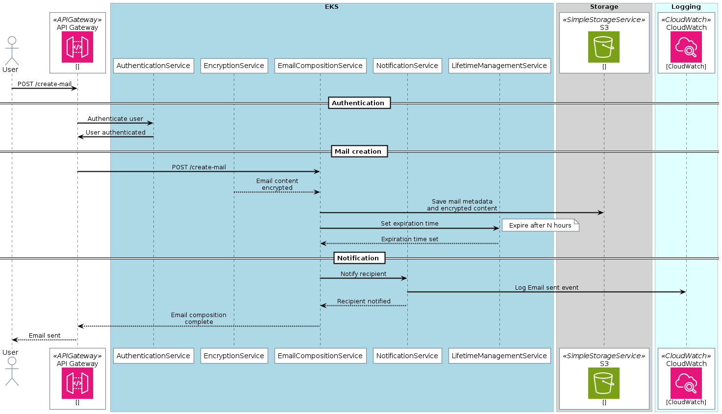
Send mail (with logging and data storage)
Now let’s add logging and data storage to the sequence diagram
1 2 3 4 5 6 7 8 9 10 11 12 13 14 15 16 17 18 19 20 21 22 23 24 25 26 27 28 29 30 31 32 33 34 35 36 37 38 39 40 41 42 43 44 45 46 47 48 49 50 51 52 53 54 55 56@startuml ' Epilogue skinparam BoxPadding 10 ' !define AWSPuml https://raw.githubusercontent.com/awslabs/aws-icons-for-plantuml/v16.0/dist !define AWSPuml /home/victor/work/repos/aws-icons-for-plantuml/dist !include AWSPuml/AWSCommon.puml !include AWSPuml/Compute/all.puml !include AWSPuml/Storage/all.puml !include AWSPuml/ManagementGovernance/CloudWatch.puml !include AWSPuml/ApplicationIntegration/APIGateway.puml !include AWSPuml/General/Internetalt1.puml !include AWSPuml/Database/DynamoDB.puml ' Components actor User as User APIGatewayParticipant(api_gateway, "API Gateway", "") box "EKS" #LightBlue participant AuthenticationService participant EncryptionService participant EmailCompositionService participant NotificationService participant LifetimeManagementService end box box "Storage" #LightGray SimpleStorageServiceParticipant(DataStorage, "S3", "") end box box "Logging" #LightCyan CloudWatchParticipant(LoggingService, "CloudWatch", "CloudWatch") end box ' Relationships User -> api_gateway: POST /create-mail == Authentication == api_gateway -> AuthenticationService: Authenticate user AuthenticationService -> api_gateway: User authenticated == Mail creation == api_gateway -> EmailCompositionService: POST /create-mail EncryptionService --> EmailCompositionService: Email content encrypted EmailCompositionService -> DataStorage: Save mail metadata and encrypted content EmailCompositionService -> LifetimeManagementService: Set expiration time note right: Expire after N hours LifetimeManagementService --> EmailCompositionService: Expiration time set == Notification == EmailCompositionService -> NotificationService: Notify recipient NotificationService -> LoggingService: Log Email sent event NotificationService --> EmailCompositionService: Recipient notified EmailCompositionService --> api_gateway: Email composition complete api_gateway --> User: Email sent @endumlCode Snippet 13: Sending mail workflow (with icons and boxes)👉 Full PlantUML Code
Outlook #
Here are some useful PlantUML related resources:
- plantuml.com
- Especially sequences, mindmaps, components
- And for software architecture: class diagrams
- real-world-plantuml.com
- The Hitchhiker’s Guide to PlantUML documentation
In the next post, we’ll cover the C4 model, a powerful framework for visualizing software and infrastructure architecture using a unified model and language. Stay tuned!
This article is part of a series.
- Part 1: Documentation as Code for Cloud
- Part 2: This Article
- Part 3: Documentation as Code for Cloud - C4 Model & Structurizr
